
")
Fast delivery within 72 Hours
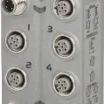
B&R X67AM1323
2 analog inputs, 2 analog outputs, each 0 to 20 mAConfigurable digital input filtersVery short cycle timesOptimal shield grounding on all channels
The modu…
Request for Quote
Shipping & Delivery
-
 Courier delivery
Our courier will deliver to the specified address
5-6 Days
From €20
-
 DHL Courier delivery
DHL courier will deliver to the specified address
2-3 Days
From €40
-
 Warranty 1 year
-
 Free 30-Day returns
Description
2 analog inputs, 2 analog outputs, each 0 to 20 mAConfigurable digital input filtersVery short cycle timesOptimal shield grounding on all channels
The module is equipped with 2 inputs and 2 outputs with 12-bit digital converter resolution. The range of the input/output signal is 0 to 20 mA.
Specification
| I/O module |
2 analog inputs, 2 analog outputs, each 0 to 20 mA |
|---|---|
| B&R ID code |
0x1466 |
| Status indicators |
I/O function per channel, supply voltage, bus function |
| Inputs |
Yes, using LED status indicator and software |
| I/O power supply |
M8, 4-pin |
| X2X Link |
M12, B-coded |
| Inputs/Outputs |
4x M12, A-coded |
| Internal I/O |
3 W |
| X2X Link power supply |
0.75 W |
| CE |
Yes |
| UKCA |
Yes |
| CRA (Cyber Resilience Act) |
In preparation |
| ATEX |
Zone 2, II 3G Ex nA IIA T5 GcIP67, Ta = 0 – Max. 60°CTÜV 05 ATEX 7201X |
| UL |
cULus E115267Industrial control equipment |
| HazLoc |
cCSAus 244665Process control equipmentfor hazardous locations Class I, Division 2, Groups ABCD, T5 |
| KC |
Yes |
| Nominal voltage |
24 VDC |
| Voltage range |
18 to 30 VDC |
| Integrated protective function |
Reverse polarity protection |
| Sensor/Actuator power supply |
Max. 12 W |
| Voltage |
I/O power supply minus voltage drop for short-circuit protection |
| Voltage drop for short-circuit protection at 0.5 A |
Max. 2 VDC |
| Summation current |
Max. 0.5 A |
| Short-circuit proof |
Yes |
| Input |
0 to 20 mA |
| Input type |
Differential input |
| Digital converter resolution |
12-bit |
| Conversion time |
400 µs for both outputs |
| Output format |
INT 0x0000 – 0x7FFF / 1 LSB = 0x0008 = 4.883 µA |
| Current |
INT 0x0000 – 0x7FFF / 1 LSB = 0x0010 = 4.883 µA |
| Load |
<300 Ω |
| Input protection |
Protection against wiring with supply voltage |
| Permissible input signal |
Max. ±30 V |
| Undershoot |
0x0000 |
| Overshoot |
0x7FFF |
| Conversion procedure |
Successive approximation |
| Gain |
0.2% |
| Offset |
0.05% |
| Max. gain drift |
0.015%/°C |
| Max. offset drift |
0.032%/°C |
| DC |
>50 dB |
| 50 Hz |
>50 dB |
| Common-mode range |
±11 V |
| Crosstalk between channels |
<-70 dB |
| Nonlinearity |
<0.1% |
| Insulation voltage between channel and bus |
500 Veff |
| Cutoff frequency |
300 Hz |
| Slope |
40 dB |
| Output |
0 to 20 mA |
| Settling time on output change over entire range |
Approx. 1 ms |
| Switch on/off behavior |
Internal enable relay for startup and errors |
| Output protection |
Protection against wiring with supply voltage, short-circuit proof |
| Load per channel |
Max. load is 400 Ω |
| Output filter |
First-order low-pass filter / cutoff frequency 1.5 kHz |
| Error caused by load change |
Max. 0.5%, from 1 Ω → 400 Ω, resistive |
| Output response when the power supply is switched on/off |
An enable relay is switched on at a defined value ≠ 0, default setting = 10 kΩ to GND |
| Current limiting |
±40 mA |
| To GND |
Yes |
| To sensor or I/O power supply |
Yes |
| Electrical isolation |
Channel isolated from busChannel not isolated from channel |
| Any |
Yes |
| 0 to 2000 m |
No limitation |
| >2000 m |
Reduction of ambient temperature by 0.5°C per 100 m |
| Degree of protection per EN 60529 |
IP67 |
| Operation |
-25 to 60°C |
| Derating |
– |
| Storage |
-40 to 85°C |
| Transport |
-40 to 85°C |
| Width |
53 mm |
| Height |
85 mm |
| Depth |
42 mm |
| Weight |
175 g |
| M8 |
Max. 0.4 Nm |
| M12 |
Max. 0.6 Nm |
Reviews
Clear filtersThere are no reviews yet.