


Fast delivery within 72 Hours
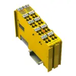
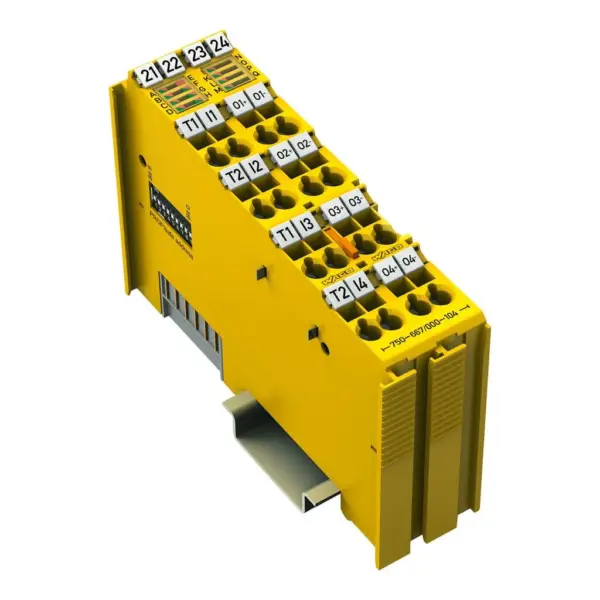
Wago 750-667/000-104
This module (Item No. 75x-667/000-104) features four power outputs (O1 … O4) and four clock-sensitive inputs (I1 … I4), enabling a functionally safe connection between fail-safe digital inputs and out…
Request for Quote
Shipping & Delivery
-
 Courier delivery
Our courier will deliver to the specified address
5-6 Days
From €20
-
 DHL Courier delivery
DHL courier will deliver to the specified address
2-3 Days
From €40
-
 Warranty 1 year
-
 Free 30-Day returns
Description
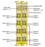
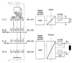
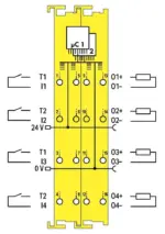
This module (Item No. 75x-667/000-104) features four power outputs (O1 … O4) and four clock-sensitive inputs (I1 … I4), enabling a functionally safe connection between fail-safe digital inputs and outputs. As a result, the module can autonomously control its safe digital outputs, enabling the implementation of safety applications up to SIL 3 / PL e without the need for a dedicated safety controller. The module has 30 virtual inputs and 30 virtual outputs, making it possible to receive additional virtual output values from a controller and to link this information to the fail-safe digital inputs. The internal logic is configured using the WAGO Safety Editor (SEDI). The sensors can be supplied directly with 24 V, or fed by two differently clocked outputs (T1 … T2). The inputs connect potential-free, emergency-off switches with contacts, safety interlock switches, mode selectors, as well as both safety sensors and semiconductor outputs (e.g., light barriers, PLC outputs). The power outputs switch both DC13 resistive and inductive loads with up to a 2A-rated current without requiring any additional external circuit. The power outputs operate in both bipolar (high-side/low-side switching) and unipolar (common potential on one side of the load) modes. The module monitors short circuits, cross circuits and 24 V power supply from separate sources. Monitoring and other safety-relevant parameters—such as operating modes, test pulse deactivation, discrepancy times, and filter times—can be configured using WAGO-I/O-CHECK. The configuration tool can be conveniently integrated into engineering systems supporting both CC2 and CC3 tool calling interfaces (TCI). The PROFIsafe address can be set using the DIP switch located on the side of the module, or via WAGO-I/O-CHECK. The module can be operated without a secure controller and is fieldbus-independent, but also supports the PROFIsafe protocol V2.6 (PROFINET®). Field and system levels are electrically isolated. Individual safety modules can be arranged in any combination when configuring the fieldbus node. If, for example, the cable length of the 24 V supply is greater than 3 m, a WAGO Filter Module or an appropriate external filter must be used for the 24 V power supply to protect the module against surge and burst (per IEC 61000-6-7 and marine applications). Additional information can be found in the product manual (available in German and English). This module (Item No. 75x-667/000-104) has been evaluated by UL in accordance with UL/CSA 61010-1, UL/CSA 61010-2-201, and UL 121201, CSA-C22.2 No. 213 standards. The functional safety evaluation was performed by TÜV Rheinland in compliance with the specified standards.
Specification
General technical data
| Protocols | Fail-safe communication via PROFIsafe V2.6 (PROFINET®); Non-fail-safe communication (PROFINET®; with functional limitations) |
|---|---|
| Configuration options | Device address adjustable via DIP switch, WAGO Safety Editor 75x, or engineering software for the safety controller; Parameters adjustable via WAGO Safety Editor 75x or engineering software for the safety controller |
| Indicators | LEDs (A–D), green/red: Status/error I1 … I4; LED (E), red: Module error; LED (F), red/green: Local bus communication; LED (G), red/green: Protocol status; LED (H), red/green: Parameterization; LEDs (I–M), red/green: Status/error O1 … O4 |
| Device specification | GSD specification: V2.4 |
| Number of F I/O modules per node (fieldbus coupler/controller) | See information in the manual about the respective fieldbus coupler/controller |
| Device-specific | Channel-granular passivation: available; Safe logic: Up to 12 functions configurable; 30 virtual inputs and outputs via process image |
| Total number of channels (module) | 8 |
| Pluggable connector | fixed |
Digital Inputs
| Number of digital inputs | 4 |
|---|---|
| Signal type | Digital |
| Signal type (voltage) | 24 VDC |
| Sensor connection | 4 x (Fail-safe input with test pulse) |
| Input characteristic | clock sensitive |
| Input characteristic | Type 1 per IEC 61131 |
| Voltage range for signal (0) | −3 … +5 VDC |
| Voltage range for signal (1) | 15 … 30 VDC |
| Input current per channel for signal (1) typ. | 3 mA |
| Signal frequency (max.) | 50 Hz |
| Input filter | 0 … 200 ms (parameterizable in steps) |
| Response times | See product manual |
| Minimum signal duration | = input filter time + test pulse duration + 2 ms |
Digital Clock Outputs
| Clock outputs | 2 |
|---|---|
| Signal type | Digital |
| Signal type (voltage) | 24 VDC |
| Output current per channel | 0.1 A |
| Test pulse duration (clock outputs) | Parameterizable between 0.5 ms and 200 ms in steps |
| Connection requirement (permissible cable length) | 200 m |
| Connection requirement (permissible cable type) | Shielded or unshielded |
| Output protection (clock outputs) | Short circuit and overload protection |
Digital outputs
| Number of digital outputs | 4 |
|---|---|
| Signal type | Digital |
| Signal type (voltage) | 24 VDC |
| Output characteristic | Parameterizable test pulses |
| Output characteristics | 2 ADC per IEC 61131-2 |
| Output current (per channel) | 2 A |
| Output current (module) | 8 A |
| Output residual current at signal “0” | < 1.0 mA |
| Output protection | Protected and short-circuit-proof per IEC 61131-2; Breaking capacity of the output protection: 200 ADC If the power-supplying network provides a short-circuit current greater than the breaking capacity, a short circuit at the output may lead to the destruction of the F I/O module.Limitation of the inductive switching voltage: See product manual |
| Response threshold (output protection) min. | 2.7 ADC |
| Response threshold (output protection) max. | 4.4 ADC |
| Parallel connection of outputs | Not possible |
| Controlling an IEC 61131‑2-compatible input | Possible; see product manual |
| Response times (max.) (outputs) | See product manual |
| Switching frequency (max.) | 0.1 Hz; Capacitive load (with 47 µF capacitive load and active discharge switched on) |
| Switching frequency (max.) (2) | 0.1 Hz; Inductive load DC 13 (50 W) per IEC 60947-5-1, see product manual |
| Capacitive load for each channel | 47 μF |
| Connection requirement (permissible cable length) (2) | 200 m |
| Connection requirement (permissible cable type) (2) | Shielded or unshielded |
| Read-back time | 1 … 500 ms (parameterizable in steps) |
| Test pulse duration (digital outputs) | 0 … 500 ms; test pulse duration is adaptively adjusted to the actuator and corresponds to the read-back time at most. |
| Response threshold (output monitoring)min. | 6.7 VDC (O1+ … O4+) |
| Response threshold (output monitoring) max. | 12 VDC (O1+ … O4+) |
Technical data
| Supply voltage (system) | 5 VDC; via data contacts |
|---|---|
| Current consumption (5 V system supply) | 120 mA |
| Overvoltage category | II |
| Supply voltage (field) | 24 VDC, SELV/PELV (-25 … +20 %); Via power jumper contacts (supply via blade contact; distribution via spring contact) |
| Current consumption, field supply (module with no external load) | 30 mA |
| Isolation (peak value) | 500 V system voltage / field level (power jumper contacts) |
| Number of incoming power jumper contacts | 2 |
| Number of outgoing power jumper contacts | 2 |
| Current carrying capacity (power jumper contacts) | 10 A |
Functional Safety
| Achievable safety classes | Logic: Cat. 4/PL e per ISO 13849; SIL 3 per IEC 61508 / EN 62061Digital inputs and outputs (without clock outputs): Single-channel: Cat. 2/PL d per ISO 13849-1; SIL 2 per IEC 61508 / EN 62061; Dual-channel: Cat. 4/PL e per ISO 13849-1; SIL 3 per IEC 61508 / EN 62061 |
|---|---|
| Safety standards | IEC 61508-1 … -7; EN ISO 13849-1; EN 62061 |
| Interface types according to ZVEI (inputs) | Drain; A, C0, C1, C2, C3 |
| Interface types per ZVEI CB24I (outputs) | Source; C0, C1, C2, C3, D0, D1, D2, D3 |
Connection data
| Connection technology: I/O | 16 x CAGE CLAMP® |
|---|---|
| Connectable conductor materials | Copper |
| Connection type | Inputs/outputs |
| Solid conductor | 0.08 … 2.5 mm² / 28 … 14 AWG |
| Fine-stranded conductor | 0.08 … 2.5 mm² / 28 … 14 AWG |
| Strip length | 8 … 9 mm / 0.31 … 0.35 inches |
Physical data
| Width | 24 mm / 0.945 inches |
|---|---|
| Height | 100 mm / 3.937 inches |
| Depth | 67.8 mm / 2.669 inches |
| Depth from upper-edge of DIN-rail | 60.6 mm / 2.386 inches |
Mechanical data
| Mounting type | DIN-35 rail |
|---|---|
| Pluggable connector | fixed |
Material data
| Housing material | Polycarbonate; polyamide 6.6 |
|---|---|
| Fire load | 1.91 MJ |
| Weight | 100.9 g |
| Conformity marking | CE; UKCA |
Environmental requirements
| Ambient temperature (operation) | 0 … +55 °C |
|---|---|
| Ambient temperature (storage) | -40 … +85 °C |
| Protection type | IP20 |
| Protection class | III |
| Pollution degree | 2 per IEC 61131-2 |
| Operating altitude | 0 … 2000 m / 0 … 6562 ft |
| Mounting position | Horizontal left, horizontal right, horizontal top, vertical top and vertical bottom |
| Relative humidity (without condensation) | 95 % |
| Vibration resistance | 4g per IEC 60068-2-6 |
| Shock resistance | 15g per IEC 60068-2-27 |
| EMC immunity to interference | per EN 61000-6-2, marine applications, EN 61000-6-7 (FS) |
| EMC emission of interference | per EN 61000-6-4, marine applications, EN 61000-6-3 |
| Exposure to pollutants | per IEC 60068-2-42 and IEC 60068-2-43 |
| Permissible H<sub>2</sub>S contaminant concentration at a relative humidity <lt/> 75 % | 10 ppm |
| Permissible SO<sub>2</sub> contaminant concentration at a relative humidity <lt/> 75 % | 25 ppm |
Commercial data
| PU (SPU) | 1 pcs |
|---|---|
| Packaging type | Box |
| Country of origin | DE |
| GTIN | 4066966509236 |
| Customs tariff number | 85371098990 |
Product Classification
| UNSPSC | 32151705 |
|---|---|
| ETIM 9.0 | EC001599 |
| ETIM 10.0 | EC001599 |
| ECCN | NO US CLASSIFICATION |
Environmental Product Compliance
| RoHS Compliance Status | Compliant,With Exemption |
|---|---|
| RoHS Exemption | 6(c), 7(a), 7(c)-I, 7(c)-II |
Reviews
Clear filtersThere are no reviews yet.