


Fast delivery within 72 Hours
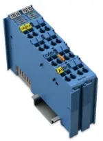
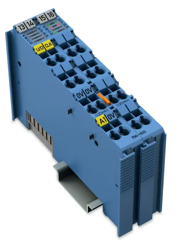
Wago 750-633
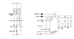
This counter records binary pulse signals with NAMUR-compliant levels and transmits the counter state to the fieldbus system. The counting direction in “up/down counter” mode can be set using the U/D…
Request for Quote
Shipping & Delivery
-
 Courier delivery
Our courier will deliver to the specified address
5-6 Days
From €20
-
 DHL Courier delivery
DHL courier will deliver to the specified address
2-3 Days
From €40
-
 Warranty 1 year
-
 Free 30-Day returns
Description
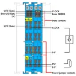
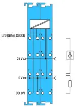
This counter records binary pulse signals with NAMUR-compliant levels and transmits the counter state to the fieldbus system. The counting direction in “up/down counter” mode can be set using the U/D input. A control byte sets or resets the counter and digital output (DO). Additionally, a limit value can be set at which the DO output is activated when this value is exceeded. The output is short-circuit-proof.Operating modes:Up counter with enable inputUp/Down Counter with U/D inputFrequency counter with enable inputPeak-time counterIndicators:Green LED (status U/D (Gate) + status CLOCK + status DO)Red LED (error U/D (Gate) + error CLOCK)Field and system levels are electrically isolated.
Specification
Notes
| Note | The up/down counter must only be operated with a 24 VDC Ex i XTR power supply!General information on explosion protection, including installation regulations, can be found in the WAGO I/O System 750/753 manuals! |
|---|
Technical data
| Item description | Up/Down Counter |
|---|---|
| Number of digital outputs | 1 |
| Number of counters | 1 |
| Signal current (0) | 1.2 mA |
| Signal current (1) | 2.1 mA |
| Input filter | 10 µs |
| Sensor supply U<sub>V</sub> | 8.2 V |
| Output voltage | 24 VDC |
| Counter depth | 32 Bit |
| Open-circuit voltage | 8.2 V |
| Short-circuit current | 8.2 mA (+/- 5 %) |
| Switching hysteresis | 0.2 mA |
| Switching frequency | 20 Hz … 50 kHz |
| Input resistance (max.) | 1000 Ω |
| Internal resistance R<sub>i</sub> | 285 Ω |
| Intrinsically safe Ex i | Yes |
| Data width | 1 x 32-bit data, 1 x 8-bit status/diagnostics |
| Supply voltage (system) | 5 VDC; via data contacts |
| Current consumption (5 V system supply) | 25 mA |
| Supply voltage (field) | 24 VDC; (Ex i power supply: Uo = max. 26.8 V); via power jumper contacts (supply via blade contact; distribution via spring contact) |
| Current consumption, field supply (module with no external load) | 31 mA |
| Power consumption P<sub>max.</sub> | 2.2 W (sensor load: 8.2 mA + actuator load: 45 mA) |
| Power loss P<sub>l</sub> | 1.7 W (sensor load: 8.2 mA + actuator load: 45 mA) |
| Isolation | 300 VAC system/supply |
| Number of incoming power jumper contacts | 2 |
| Number of outgoing power jumper contacts | 2 |
| Current carrying capacity (power jumper contacts) | 1 A |
| Indicators | LED (A, D, E) green: U/D (Gate), DO, CLOCK; LED (B, F) red: Error U/D (Gate), Error CLOCK |
Explosion protection
| Identification | ATEX: II 3 (1) G Ex ec [ia Ga] IIC T4 Gc; II (1) D [Ex ia Da] IIIC; I (M1) [Ex ia Ma] I, IECEx/INMETRO: Ex ec [ia Ga] IIC T4 Gc; [Ex ia Da] IIIC; [Ex ia Ma] I, cULus (Zone classified): Cl I Zn 2 AEx nA [ia Ga] IIC T4 Gc; Cl I Zn 2 AEx nA [ia IIIC] IIC T4 Gc; Ex nA [ia Ga] IIC T4 Gc X; Ex nA [ia IIIC] IIC T4 Gc X, cULus (Devision classified): Class I, Div. 2, Group A B C D, T4 |
|---|---|
| Ex standard | EN IEC 60079-0, -7, -11 |
| Safety data (input) | Uo = 12 V; Io = 13.5 mA; Po = 40.5 mW; linear characteristic curve |
| Reactances of Ex ia IIC inputs | Lo = 100 mH; Co = 1.4 µF |
| Reactances of Ex ia IIB inputs | Lo = 100 mH; Co = 9 µF |
| Reactances of Ex ia IIA inputs | Lo = 100 mH; Co = 36 µF |
| Reactances of Ex ia I inputs | Lo = 100 mH; Co = 38 µF |
| Safety data (output) | Uo = 26.8 V; Io = 96.7 mA; Po = 648 mW; linear characteristic curve |
| Reactances of Ex ia IIC output | Lo = 3.8 mH; Co = 92 nF |
| Reactances of Ex ia IIB output | Lo = 115.2 mH; Co = 720 nF |
| Reactances of Ex ia IIA output | Lo = 30.41 mH; Co = 2.37 µF |
| Reactances of Ex ia I output | Lo = 49.9 mH; Co = 4.2 µF |
| Reactances (note) | Reactances without accounting for the concurrence of capacitance (Co) and inductance (Lo) |
Connection data
| Connection technology: I/O | 16 x CAGE CLAMP® |
|---|---|
| Connectable conductor materials | Copper |
| Connection type | Inputs/outputs |
| Solid conductor | 0.08 … 2.5 mm² / 28 … 14 AWG |
| Fine-stranded conductor | 0.08 … 2.5 mm² / 28 … 14 AWG |
| Strip length | 8 … 9 mm / 0.31 … 0.35 inches |
Physical data
| Width | 24 mm / 0.945 inches |
|---|---|
| Height | 100 mm / 3.937 inches |
| Depth | 67.8 mm / 2.669 inches |
| Depth from upper-edge of DIN-rail | 60.6 mm / 2.386 inches |
Mechanical data
| Mounting type | DIN-35 rail |
|---|
Material data
| Color | blue |
|---|---|
| Housing material | Polycarbonate; polyamide 6.6 |
| Fire load | 1.981 MJ |
| Weight | 88.2 g |
| Conformity marking | CE |
Environmental requirements
| Ambient temperature (operation) | 0 … +55 °C |
|---|---|
| Ambient temperature (storage) | -25 … +85 °C |
| Protection type | IP20 |
| Pollution degree | 2 per IEC 61131-2 |
| Operating altitude | 0 … 2000 m / 0 … 6562 ft |
| Mounting position | Horizontal left, horizontal right, horizontal top, horizontal bottom, vertical top and vertical bottom |
| Relative humidity (without condensation) | 95 % |
| Vibration resistance | 4g per IEC 60068-2-6 |
| Shock resistance | 15g per IEC 60068-2-27 |
| EMC immunity to interference | per EN 61000-6-2, marine applications |
| EMC emission of interference | per EN 61000-6-3, marine applications |
| Exposure to pollutants | per IEC 60068-2-42 and IEC 60068-2-43 |
| Permissible H<sub>2</sub>S contaminant concentration at a relative humidity <lt/> 75 % | 10 ppm |
| Permissible SO<sub>2</sub> contaminant concentration at a relative humidity <lt/> 75 % | 25 ppm |
Commercial data
| Product Group | 15 (I/O System) |
|---|---|
| PU (SPU) | 1 pcs |
| Packaging type | Box |
| Country of origin | DE |
| GTIN | 4050821386926 |
| Customs tariff number | 85389099990 |
Product Classification
| UNSPSC | 39121529 |
|---|---|
| eCl@ss 10.0 | 27-24-26-05 |
| eCl@ss 9.0 | 27-24-26-05 |
| ETIM 9.0 | EC001601 |
| ETIM 10.0 | EC001601 |
| ECCN | NO US CLASSIFICATION |
Environmental Product Compliance
| CAS-No. | 1303-86-2, 1317-36-8, 7439-92-1 |
|---|---|
| REACH Candidate List Substance | Diboron trioxide, Lead, Lead monoxide |
| RoHS Compliance Status | Compliant,With Exemption |
| RoHS Exemption | 6(c), 7(a), 7(c)-I, 7(c)-II |
| SCIP notification number (Bulgaria) | 5b4703c5-63a4-4a2f-840e-875112670b16 |
| SCIP notification number (Czech Republic) | 0dfd5047-b7df-4e54-811a-a9b844981321 |
Reviews
Clear filtersThere are no reviews yet.