


Fast delivery within 72 Hours
Wago 750-1689
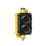
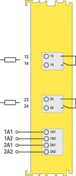
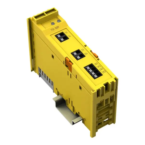
The module (Item No. 750-1689) has two independently switchable relay outputs (RO1 … RO2) and is particularly suitable for applications that, e.g., individually electrically isolated Outputs are req…
Request for Quote
Shipping & Delivery
-
 Courier delivery
Our courier will deliver to the specified address
5-6 Days
From €20
-
 DHL Courier delivery
DHL courier will deliver to the specified address
2-3 Days
From €40
-
 Warranty 1 year
-
 Free 30-Day returns
Description
The module (Item No. 750-1689) has two independently switchable relay outputs (RO1 … RO2) and is particularly suitable for applications that, e.g., individually electrically isolated Outputs are required, high loads must be switched or controlled with different voltage types (e.g., DC and AC voltage). The module supports operating voltages up to 250 VAC and 250 VDC.The electrically isolated outputs can be freely combined with each other, so that Cat. 2 or Cat. 4 architectures up to SIL3 or PLe are possible. Details on possible wiring variants can be found in the product manual.The relay outputs must be controlled via safe digital outputs (e.g., the outputs of the 75x-667/000-004, 750-1665/000-004 module), in which case an unsafe enable of the relay outputs must also be provided via the process image.The status of the safe relay outputs and the temperature for each relay are detected and transmitted to the controller via the non-safe process image, where they must be evaluated as diagnostics.The field and system levels are electrically isolated from each other.The individual safe modules can be arranged in any configuration in the fieldbus node.The module (Item No. 750-1689) was evaluated by UL in accordance with UL/CSA 61010-1, UL/CSA 61010-2-201 and UL 121201, CSA-C22.2 No. 213. The functional safety assessment according to the above standards was carried out by TÜV Rheinland.
Specification
Technical data
| Indicators | LED (A/B) green: Status RO1 ... RO2 |
|---|---|
| Number of F I/O modules per node (fieldbus coupler/controller) | See information in the manual about the respective fieldbus coupler/controller |
| Supply voltage (system) | 5 VDC; via data contacts |
| Current consumption (5 V system supply) | 15 mA |
Relay control signals
| Signal type | Digital |
|---|---|
| Cable length (max.) | 3 m |
| Reverse voltage protection | Yes |
| Input voltage (max.) | 24 VDC (-25 … +30 %) |
| Input current (max.) | 15 mA (Control current per channel max.) |
| Test pulse duration (max.) | 1 ms |
Relay outputs
| Number of digital outputs | 2 |
|---|---|
| Output circuit design | 2 make contacts; relay |
| Signal type | Digital |
| Actuator connection | 2 x (2-wire) |
| Output characteristic | potential-free |
| Switching voltage (max.) | 250 VAC; 250 VDC |
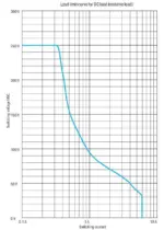
| Switching power | AC: 0.1 VA ... 1500 VA; DC: 200 W; see load limit curve |
| Output current (per channel) | 6 A at 250 VAC (resistive load);6 A at 31,2 VDC (resistive load);3 A at 60 VDC (resistive load);0,8 A at 110 VDC (resistive load);0,3 A at 250 VDC (resistive load);2 A at 31,2 VDC (Pilot Duty);UL: R300 Pilot Duty according to UL508;UL: B300 Pilot Duty according to UL508 |
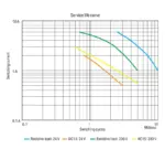
| Switching capacity | AC-15: 3 A / 250 VAC; DC-13: 2 A / 31.2 VDC |
| Output current (module) | 12 A |
| Limitation of the inductive switch-off voltage | nein |
| Drop-out time (typ.) | 50 ms |
| Pull-in time (max.) | 10 ms |
| Short-circuit withstand capacity | 1 kA / 250 VAC IEC/EN 60947-5-1 |
| Fuse | Each channel requires its own external fuse; max. 10 A slow; min. approved for the switching voltage used |
| Switching frequency (max.) | 1 Hz; Resistive load |
| Switching frequency (max.) (2) | 0.1 Hz; Inductive load |
| Contact load | 2 mA (min.); 10 mA after a single overflow of 300 mA load current or a switching power of 12 W or 12 VA |
| Diagnostics | Relay status in the process image via force-guided contact |
| Electrical switching operations (min.) (at max. resistive load) | 1 x 10⁶ switching operations |
| Mechanical switching operations (min.) (at max. resistive load) | 40 x 10⁶ switching operations |
| Contact material | AgNi + 5μm Au |
| B10d values (resistive load) | Resistive load (at 230 VAC); 6 A: 600,000; 3 A: 6,000,000; 2 A: 10,000,000; 1 A: 12,000,000 switching cycles, Resistive load (at 24 VDC); 6 A: 4,000,000; 3 A: 10,000,000; 2 A: 14,000,000; 1 A: 20,000,000 switching cycles |
| B10d (15 AAC) | AC-15 (at 230 VAC); 3 A: 6,000,000; 2 A: 10,000,000; 1 A: 12,000,000; 0.5 A: 20,000,000 switching cycles |
| B10d (DC 13) | DC-13 (at 24 VDC); 2 A: 4,000,000; 1 A: 8,000,000; 0.5 A: 15,000,000 switching cycles |
Safety and protection
| System voltage | ≤ 250 V |
|---|---|
| Note on system voltage | The system voltage corresponds to the line-to-neutral voltage derived from conventional mains power supply systems. |
Insulation coordination
| Overvoltage category | per EN 60664-1: III; per EN/UL 61010-2-201: II |
|---|---|
| Insulation type | Relay: Reinforced insulation; Channel/channel: Reinforced insulation; Control/system: Functional insulation |
Test voltage
| Test voltage | Test voltage (relay): 3.51 kVAC, 50/60 Hz, 1 min.; Test voltage (control/system): 500 VDC, 1 min. |
|---|---|
| Rated impulse withstand voltage | 6 kV (relay) |
Functional Safety
| Achievable safety classes | Two-Channel Cat. 4/PL e per EN ISO 13849-1; SIL 3 per IEC 61508 / EN 62061; Single-Channel Cat. 2/PL d per EN ISO 13849-1; SIL 2 per IEC 61508 / EN 62061 |
|---|---|
| Safety standards | IEC 61508-1 … -7; EN ISO 13849-1; EN 62061; DIN EN 61810-1, DIN EN 61810-3 |
| Service life | 20. Jahre |
Connection data
| Connection technology: I/O | 8 x Push-in CAGE CLAMP® (outputs) |
|---|---|
| Connectable conductor materials | Copper |
| Connection type | Output |
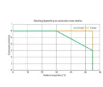
| Solid conductor | 0.14 … 1.5 mm² / 28 … 16 AWG |
| Fine-stranded conductor; with insulated ferrule | 0.25 … 0.75 mm² |
| Fine-stranded conductor; with uninsulated ferrule | 0.25 … 1.5 mm² |
| Strip length | 8 … 9 mm / 0.31 … 0.35 inches |
Physical data
| Width | 24 mm / 0.944 inches |
|---|---|
| Height | 100 mm / 3.937 inches |
| Depth | 69.8 mm / 2.748 inches |
| Depth from upper-edge of DIN-rail | 62.6 mm / 2.465 inches |
Mechanical data
| Mounting type | DIN-35 rail |
|---|---|
| Pluggable connector | fixed |
Material data
| Housing material | Polycarbonate; polyamide 6.6 |
|---|---|
| Fire load | 1.374 MJ |
| Weight | 93.5 g |
Environmental requirements
| Ambient temperature (operation) | 0 … +55 °C |
|---|---|
| Ambient temperature (storage) | -40 … +85 °C |
| Protection type | IP20 |
| Pollution degree | 2 |
| Protection class | II |
| Operating altitude | 0 … 2000 m / 0 … 6562 ft |
| Mounting position | Horizontal left, horizontal right, horizontal top, vertical top and vertical bottom |
| Relative humidity (without condensation) | 95 % |
| Vibration resistance | 4g per IEC 60068-2-6 |
| Shock resistance | 15g per IEC 60068-2-27 |
| EMC immunity to interference | Per EN 61000-6-2; marine applications; EN 61000-6-7 (FS); EN 61326-3-1:2017 |
| EMC emission of interference | per EN 61000-6-4, marine applications, EN 61000-6-3 |
| Exposure to pollutants | per IEC 60068-2-42 and IEC 60068-2-43 |
| Permissible H<sub>2</sub>S contaminant concentration at a relative humidity <lt/> 75 % | 10 ppm |
| Permissible SO<sub>2</sub> contaminant concentration at a relative humidity <lt/> 75 % | 25 ppm |
Commercial data
| PU (SPU) | 1 pcs |
|---|---|
| Packaging type | Box |
| Country of origin | DE |
| GTIN | 4066966764451 |
| Customs tariff number | 85371098990 |
Product Classification
| ETIM 9.0 | EC001599 |
|---|---|
| ETIM 10.0 | EC001599 |
| ECCN | NO US CLASSIFICATION |
Environmental Product Compliance
| RoHS Compliance Status | Compliant,No Exemption |
|---|
Reviews
Clear filtersThere are no reviews yet.