


Fast delivery within 72 Hours
Wago 2624-3502
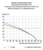
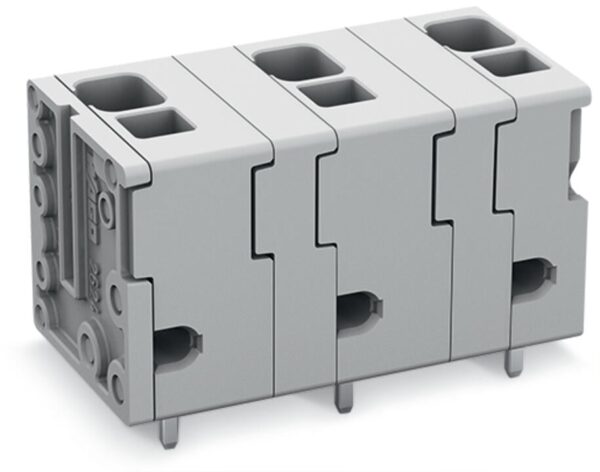
PCB terminal block, 2624 Series, 90 °conductor entry to boardOur PCB terminal block (item number 2624-3502) is the perfect way to connect conductors quickly and securely. You can count on proven safet…
Request for Quote
Shipping & Delivery
-
 Courier delivery
Our courier will deliver to the specified address
5-6 Days
From €20
-
 DHL Courier delivery
DHL courier will deliver to the specified address
2-3 Days
From €40
-
 Warranty 1 year
-
 Free 30-Day returns
Description
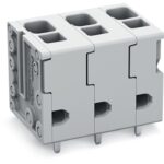
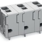
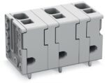
PCB terminal block, 2624 Series, 90 °conductor entry to boardOur PCB terminal block (item number 2624-3502) is the perfect way to connect conductors quickly and securely. You can count on proven safety with these PCB terminal blocks, perfect for a wide range of applications when designing your devices. Our PCB terminal block is rated for 1000 V and is designed for use with a rated current of up to 41 A. It can therefore be used in high-load applications. Strip lengths must be between 10 mm and 12 mm when connecting conductors to this PCB terminal block. This product features one conductor terminal and utilizes Push-in CAGE CLAMP®. Push-in CAGE CLAMP® connection technology is ideal for connecting all conductor types. It allows direct insertion of both solid and fine-stranded conductors with ferrules without needing to use any tools—all thanks to its pluggable design. Dimensions: 18 x 20.3 x 15.4 mm (width x height x depth). This PCB terminal block is suitable for conductor cross sections ranging from 0.2 mm² to 6 mm². Up to two potentials / two poles can be connected to this terminal strip using two clamping points on one level. The gray housing is made of polyamide (PA66) for insulation, the clamping spring is made of chrome-nickel spring steel (CrNi), and the contacts are made of electrolytic copper (ECu). The contact surface is coated with tin. This PCB terminal block is operated with an operating tool. The PCB terminal block is designed for THT soldering. These PCB terminal blocks are mounted using feed-through mounts.. Insert the conductor at an angle of 90°.. The solder pins measure 0.8 x 1 mm in cross-section and 4 mm in length and are arranged over the entire terminal strip (in-line). There are two solder pins per potential.
Specification
Notes
| Variants: | Other pole numbers, Direct marking, Other colors, Other versions (or variants) can be requested from WAGO Sales or configured at https://configurator.wago.com/. |
|---|
Electrical data - Ratings per IEC/EN
| Ratings per | IEC/EN 60664-1 |
|---|---|
| Nominal voltage (III/3) | 1000 V |
| Rated impulse withstand voltage (III / 3) | 8 kV |
| Rated voltage (III/2) | 1000 V |
| Rated impulse withstand voltage (III/2) | 8 kV |
| Nominal voltage (II/2) | 1000 V |
| Rated impulse withstand voltage (II/2) | 8 kV |
| Rated current | 41 A |
| Legend (ratings) | (III / 2) ≙ Overvoltage category III / Pollution degree 2 |
| Ratings per | IEC/EN 60664-1 / IEC/EN 60664-1 / IEC/EN 60664-1 |
| Overvoltage category | III / III / II |
| Pollution degree | 3 / 2 / 2 |
| Nominal voltage | 1000 V / 1000 V / 1000 V |
| Rated impulse withstand voltage | 8 kV / 8 kV / 8 kV |
| Rated current | 41 A / 41 A / 41 A |
Electrical data - Ratings per UL
| Approvals per | UL 1059 |
|---|---|
| Rated voltage UL (Use Group B) | 600 V |
| Rated current UL (Use Group B) | 26 A |
| Rated voltage UL (Use Group C) | 600 V |
| Rated current UL (Use Group C) | 26 A |
| Approvals per | UL 1059 / UL 1059 / UL 1059 |
| Use group | B / C / D |
| Rated voltage | 600 V / 600 V |
| Rated current | 26 A / 26 A |
Electrical data - Ratings per CSA
| Approvals per | CSA |
|---|---|
| Rated voltage CSA (Use Group B) | 600 V |
| Rated current CSA (Use Group B) | 26 A |
| Rated voltage CSA (Use Group C) | 600 V |
| Rated current CSA (Use Group C) | 26 A |
| Approvals per | CSA / CSA / CSA |
| Use group | B / C / D |
| Rated voltage | 600 V / 600 V |
| Rated current | 26 A / 26 A |
Connection data
| Clamping units | 2 |
|---|---|
| Total number of potentials | 2 |
| Number of connection types | 1 |
| Number of levels | 1 |
Connection data - Connection 1
| Connection technology | Push-in CAGE CLAMP® |
|---|---|
| Actuation type | Operating tool |
| Solid conductor | 0.2 … 6 mm² / 24 … 10 AWG |
| Fine-stranded conductor | 0.2 … 6 mm² / 24 … 10 AWG |
| Fine-stranded conductor; with insulated ferrule | 0.25 … 2.5 mm² |
| Fine-stranded conductor; with uninsulated ferrule | 0.25 … 2.5 mm² |
| Fine-stranded conductor; with twin ferrule | 0.25 … 1.5 mm² |
| Strip length | 10 … 12 mm / 0.39 … 0.47 inches |
| Conductor connection direction to PCB | 90 ° |
| Pole number | 2 |
Physical data
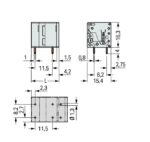
| Pin spacing | 11.5 mm / 0.453 inches |
|---|---|
| Width | 18 mm / 0.709 inches |
| Height | 20.3 mm / 0.799 inches |
| Height from the surface | 16.3 mm / 0.642 inches |
| Depth | 15.4 mm / 0.606 inches |
| Solder pin length | 4 mm |
| Solder pin dimensions | 0.8 x 1 mm |
| Drilled hole diameter with tolerance | 1.3 (+0.1) mm |
Mechanical data
| Mounting type | Feed-through mounting |
|---|
PCB contact
| PCB contact | THT |
|---|---|
| Solder pin arrangement | over the entire terminal strip (in-line) |
| Number of solder pins per potential | 2 |
Material data
| Note (material data) | Information on material specifications can be found here |
|---|---|
| Color | gray |
| Material group | I |
| Insulation material (main housing) | Polyamide (PA66) |
| Flammability class per UL94 | V0 |
| Clamping spring material | Chrome-nickel spring steel (CrNi) |
| Contact material | Electrolytic copper (ECu) |
| Contact plating | Tin |
| Fire load | 0.046 MJ |
| Weight | 4.3 g |
Environmental requirements
| Limit temperature range | -60 … +105 °C |
|---|---|
| Processing temperature | -35 … +60 °C |
| Continuous operating temperature | -60 … +105 °C |
Commercial data
| PU (SPU) | 110 pcs |
|---|---|
| Packaging type | box |
| Country of origin | PL |
| GTIN | 4066966493191 |
| Customs tariff number | 85369010000 |
Product Classification
| UNSPSC | 39121409 |
|---|---|
| eCl@ss 10.0 | 27-44-04-01 |
| eCl@ss 9.0 | 27-44-04-01 |
| ETIM 9.0 | EC002643 |
| ETIM 10.0 | EC002643 |
| ECCN | NO US CLASSIFICATION |
Environmental Product Compliance
| RoHS Compliance Status | Compliant,No Exemption |
|---|
Reviews
Clear filtersThere are no reviews yet.