


Fast delivery within 72 Hours
Wago 2616-1101
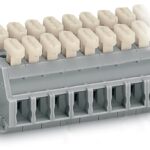
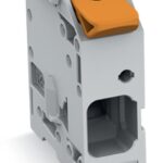
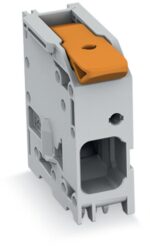
PCB terminal block, 2616 Series, 0 °conductor entry to boardThis PCB terminal block (item number 2616-1101) is designed for quick and simple connections. You can count on tried and tested safety with…
Request for Quote
Shipping & Delivery
-
 Courier delivery
Our courier will deliver to the specified address
5-6 Days
From €20
-
 DHL Courier delivery
DHL courier will deliver to the specified address
2-3 Days
From €40
-
 Warranty 1 year
-
 Free 30-Day returns
Description
PCB terminal block, 2616 Series, 0 °conductor entry to boardThis PCB terminal block (item number 2616-1101) is designed for quick and simple connections. You can count on tried and tested safety with these PCB terminal blocks, perfect for a wide variety of applications when designing your devices. This PCB terminal block has a rated voltage of 1000 V and can handle currents up to 76 A, making it ideal for high-load applications. Strip lengths must be between 18 mm and 20 mm when connecting conductors to this PCB terminal block. Featuring one conductor terminal along with Push-in CAGE CLAMP®, this product outperforms the competition. Push-in CAGE CLAMP® technology provides a universal connection solution for all conductor types. It allows both solid and fine-stranded conductors with ferrules to be inserted directly into the clamping point without the need for tools. Dimensions: 12.8 x 37.2 x 32 mm (width x height x depth). Depending on the conductor type, this PCB terminal block is ideal for conductor cross sections ranging from 0.75 mm² to 16 mm². Up to one potential / one pole can be connected to this terminal block using one clamping point on one level. The gray housing is made of polyamide (PA66) for insulation, the contacts are made of electrolytic copper (ECu), and the clamping spring is made of chrome-nickel spring steel (CrNi). The contact surface is coated with tin. A lever is used to operate this PCB terminal block. THT is used to solder the PCB terminal block. Insert the conductor at a 0° angle.. The solder pins measure 1.2 x 1.2 mm in cross-section and 4 mm in length and are arranged over the entire terminal strip (in-line). There are six solder pins per potential.
Specification
Notes
| Note | The inherent stability of a single-pole PCB terminal block is less than that of a multi-pole terminal strip. The customer must therefore ensure that these terminal blocks are protected against excessive mechanical stress (e.g., torsional or bending stress), both when connecting the conductor and during subsequent use, for example by providing additional support, shortly holding the connected conductor and appropriate actuation instructions. |
|---|---|
| Variants: | Other pole numbers, Direct marking, Other colors, Other versions (or variants) can be requested from WAGO Sales or configured at https://configurator.wago.com/. |
Electrical data - Ratings per IEC/EN
| Ratings per | IEC/EN 60664-1 |
|---|---|
| Nominal voltage (III/3) | 1000 V |
| Rated impulse withstand voltage (III / 3) | 8 kV |
| Rated voltage (III/2) | 1000 V |
| Rated impulse withstand voltage (III/2) | 8 kV |
| Nominal voltage (II/2) | 1000 V |
| Rated impulse withstand voltage (II/2) | 8 kV |
| Rated current | 76 A |
| Legend (ratings) | (III / 2) ≙ Overvoltage category III / Pollution degree 2 |
| Ratings per | IEC/EN 60664-1 / IEC/EN 60664-1 / IEC/EN 60664-1 |
| Overvoltage category | III / III / II |
| Pollution degree | 3 / 2 / 2 |
| Nominal voltage | 1000 V / 1000 V / 1000 V |
| Rated impulse withstand voltage | 8 kV / 8 kV / 8 kV |
| Rated current | 76 A / 76 A / 76 A |
Electrical data - Ratings per UL
| Approvals per | UL 1059 |
|---|---|
| Rated voltage UL (Use Group B) | 600 V |
| Rated current UL (Use Group B) | 78 A |
| Rated voltage UL (Use Group C) | 600 V |
| Rated current UL (Use Group C) | 78 A |
| Approvals per | UL 1059 / UL 1059 / UL 1059 |
| Use group | B / C / D |
| Rated voltage | 600 V / 600 V |
| Rated current | 78 A / 78 A |
Electrical data - Ratings per CSA
| Approvals per | CSA |
|---|---|
| Rated voltage CSA (Use Group B) | 600 V |
| Rated current CSA (Use Group B) | 72 A |
| Rated voltage CSA (Use Group C) | 1000 V |
| Rated current CSA (Use Group C) | 72 A |
| Approvals per | CSA / CSA / CSA |
| Use group | B / C / D |
| Rated voltage | 600 V / 1000 V |
| Rated current | 72 A / 72 A |
Connection data
| Clamping units | 1 |
|---|---|
| Total number of potentials | 1 |
| Number of connection types | 1 |
| Number of levels | 1 |
Connection data - Connection 1
| Connection technology | Push-in CAGE CLAMP® |
|---|---|
| Actuation type | Lever |
| Solid conductor | 0.75 … 16 mm² / 18 … 4 AWG |
| Fine-stranded conductor | 0.75 … 25 mm² / 18 … 4 AWG |
| Fine-stranded conductor; with insulated ferrule | 0.75 … 16 mm² |
| Fine-stranded conductor; with uninsulated ferrule | 0.75 … 16 mm² |
| Fine-stranded conductor; with twin ferrule | 0.75 … 6 mm² |
| Strip length | 18 … 20 mm / 0.71 … 0.79 inches |
| Conductor connection direction to PCB | 0 ° |
| Pole number | 1 |
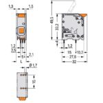
Physical data
| Pin spacing | 10 mm / 0.394 inches |
|---|---|
| Width | 12.8 mm / 0.504 inches |
| Height | 37.2 mm / 1.465 inches |
| Height from the surface | 33.2 mm / 1.307 inches |
| Depth | 32 mm / 1.26 inches |
| Solder pin length | 4 mm |
| Solder pin dimensions | 1.2 x 1.2 mm |
| Drilled hole diameter with tolerance | 1.7 (+0.1) mm |
PCB contact
| PCB contact | THT |
|---|---|
| Solder pin arrangement | Over the entire terminal strip (in-line) |
| Number of solder pins per potential | 6 |
Material data
| Note (material data) | Information on material specifications can be found here |
|---|---|
| Color | gray |
| Material group | I |
| Insulation material (main housing) | Polyamide (PA66) |
| Flammability class per UL94 | V0 |
| Clamping spring material | Chrome-nickel spring steel (CrNi) |
| Contact material | Electrolytic copper (ECu) |
| Contact plating | Tin |
| Fire load | 0.176 MJ |
| Actuator color | orange |
| Weight | 10.8 g |
Environmental requirements
| Limit temperature range | -60 … +105 °C |
|---|---|
| Processing temperature | -35 … +60 °C |
Commercial data
| PU (SPU) | 100 pcs |
|---|---|
| Packaging type | box |
| Country of origin | PL |
| GTIN | 4055143692762 |
| Customs tariff number | 85369010000 |
Product Classification
| UNSPSC | 39121409 |
|---|---|
| eCl@ss 10.0 | 27-44-04-01 |
| eCl@ss 9.0 | 27-44-04-01 |
| ETIM 9.0 | EC002643 |
| ETIM 10.0 | EC002643 |
| ECCN | NO US CLASSIFICATION |
Environmental Product Compliance
| RoHS Compliance Status | Compliant,No Exemption |
|---|
Reviews
Clear filtersThere are no reviews yet.