


Fast delivery within 72 Hours
Wago 2604-1104
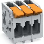
PCB terminal block, 2604 Series, solder pin dimensions 0.8 x 1 mmThis PCB terminal block (item number 2604-1104) is designed for simple and secure connections. You can count on proven safety with thes…
Request for Quote
Shipping & Delivery
-
 Courier delivery
Our courier will deliver to the specified address
5-6 Days
From €20
-
 DHL Courier delivery
DHL courier will deliver to the specified address
2-3 Days
From €40
-
 Warranty 1 year
-
 Free 30-Day returns
Description
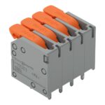
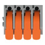
PCB terminal block, 2604 Series, solder pin dimensions 0.8 x 1 mmThis PCB terminal block (item number 2604-1104) is designed for simple and secure connections. You can count on proven safety with these PCB terminal blocks, perfect for a wide range of applications when designing your devices. Our PCB terminal block is rated for 400 V and is designed for use with a rated current of up to 32 A. It is therefore suitable for high-load applications. Conductors can only be connected to this PCB terminal block if their strip length is between 9 mm and 11 mm. This product features one conductor terminal and utilizes Push-in CAGE CLAMP®. Push-in CAGE CLAMP® technology provides a universal connection solution for any type of conductor. It allows both solid and fine-stranded conductors with ferrules to be inserted directly into the clamping point without the need for tools. The item’s dimensions are 22.4 x 20.7 x 19.2 mm (width x height x depth). This PCB terminal block is suitable for conductor cross sections ranging from 0.2 mm² to 4 mm². It has one level. You can connect four potentials / four poles using the four clamping points. The contacts are made of electrolytic copper (ECu), the gray housing is made of polyamide (PA66) for insulation, and the clamping spring is made of chrome-nickel spring steel (CrNi). The contact surface is coated with tin. A lever is used to operate this PCB terminal block. THT is used to assemble the PCB terminal block. Insert the conductor into the board at an angle of 0°.. The solder pins are organized over the entire terminal strip (in-line). They are 0.8 x 1 mm cross-section and 4 mm in length. Each potential has two solder pins.
Specification
Notes
| Variants: | Other pole numbers, Direct marking, Other colors, Other versions (or variants) can be requested from WAGO Sales or configured at https://configurator.wago.com/. |
|---|
Electrical data - Ratings per IEC/EN
| Ratings per | IEC/EN 60664-1 |
|---|---|
| Nominal voltage (III/3) | 320 V |
| Rated impulse withstand voltage (III / 3) | 4 kV |
| Rated voltage (III/2) | 400 V |
| Rated impulse withstand voltage (III/2) | 4 kV |
| Nominal voltage (II/2) | 630 V |
| Rated impulse withstand voltage (II/2) | 4 kV |
| Rated current | 32 A |
| Legend (ratings) | (III / 2) ≙ Overvoltage category III / Pollution degree 2 |
| Ratings per | IEC/EN 60664-1 / IEC/EN 60664-1 / IEC/EN 60664-1 |
| Overvoltage category | III / III / II |
| Pollution degree | 3 / 2 / 2 |
| Nominal voltage | 320 V / 400 V / 630 V |
| Rated impulse withstand voltage | 4 kV / 4 kV / 4 kV |
| Rated current | 32 A / 32 A / 32 A |
Electrical data - Ratings per UL
| Approvals per | UL 1059 |
|---|---|
| Rated voltage UL (Use Group B) | 300 V |
| Rated current UL (Use Group B) | 20 A |
| Rated voltage UL (Use Group D) | 300 V |
| Rated current UL (Use Group D) | 10 A |
| Approvals per | UL 1059 / UL 1059 / UL 1059 |
| Use group | B / C / D |
| Rated voltage | 300 V / 300 V |
| Rated current | 20 A / 10 A |
Electrical data - Ratings per CSA
| Approvals per | CSA |
|---|---|
| Rated voltage CSA (Use Group B) | 300 V |
| Rated current CSA (Use Group B) | 20 A |
| Rated voltage CSA (Use Group D) | 300 V |
| Rated current CSA (Use Group D) | 5 A |
| Approvals per | CSA / CSA / CSA |
| Use group | B / C / D |
| Rated voltage | 300 V / 300 V |
| Rated current | 20 A / 5 A |
Connection data
| Clamping units | 4 |
|---|---|
| Total number of potentials | 4 |
| Number of connection types | 1 |
| Number of levels | 1 |
Connection data - Connection 1
| Connection technology | Push-in CAGE CLAMP® |
|---|---|
| Actuation type | Lever |
| Solid conductor | 0.2 … 4 mm² / 24 … 12 AWG |
| Fine-stranded conductor | 0.2 … 4 mm² / 24 … 12 AWG |
| Fine-stranded conductor; with insulated ferrule | 0.25 … 2.5 mm² |
| Fine-stranded conductor; with uninsulated ferrule | 0.25 … 2.5 mm² |
| Fine-stranded conductor; with twin ferrule | 0.25 … 1.5 mm² |
| Strip length | 9 … 11 mm / 0.35 … 0.43 inches |
| Conductor connection direction to PCB | 0 ° |
| Pole number | 4 |
Physical data
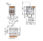
| Pin spacing | 5 mm / 0.197 inches |
|---|---|
| Width | 22.4 mm / 0.882 inches |
| Height | 20.7 mm / 0.815 inches |
| Height from the surface | 16.7 mm / 0.657 inches |
| Depth | 19.2 mm / 0.756 inches |
| Solder pin length | 4 mm |
| Solder pin dimensions | 0.8 x 1 mm |
| Drilled hole diameter with tolerance | 1.3 (+0.1) mm |
PCB contact
| PCB contact | THT |
|---|---|
| Solder pin arrangement | over the entire terminal strip (in-line) |
| Number of solder pins per potential | 2 |
Material data
| Note (material data) | Information on material specifications can be found here |
|---|---|
| Color | gray |
| Material group | I |
| Insulation material (main housing) | Polyamide (PA66) |
| Flammability class per UL94 | V0 |
| Clamping spring material | Chrome-nickel spring steel (CrNi) |
| Contact material | Electrolytic copper (ECu) |
| Contact plating | Tin |
| Fire load | 0.166 MJ |
| Actuator color | orange |
| Weight | 6.2 g |
Environmental requirements
| Limit temperature range | -60 … +105 °C |
|---|---|
| Processing temperature | -35 … +60 °C |
| Continuous operating temperature | -60 … +105 °C |
Environmental requirements - Environmental Testing
| Test specification: <br/>Railway applications –<br/>Rolling stock –<br/>Electronic equipment | DIN EN 50155 (VDE 0115-200):2022-06 |
|---|---|
| Test procedure: <br/>Railway applications – <br/>Rolling stock equipment – <br/>Vibration and shock tests | DIN EN 61373 (VDE 0115-0106):2011-04 |
| Spectrum/Mounting location | Service life test, Category 1, Class A/B |
| Functional test with noise-like oscillations | Test passed according to Section 8 of the standard |
| Frequency | f1 = 5 Hz to f2 = 150 Hz |
| Acceleration | 0.101g (highest test level used for all axes) |
| Test duration per axis | 10 min. |
| Test directions | X, Y and Z axes |
| Monitoring of contact faults and interruptions | Passed |
| Voltage drop measurement before and after each axis | Passed |
| Simulated service life test through increased levels of noise-like oscillations | Test passed according to Section 9 of the standard |
| Frequency | f1 = 5 Hz to f2 = 150 Hz |
| Acceleration | 0.572g (highest test level used for all axes) |
| Test duration per axis | 5 h |
| Test directions | X, Y and Z axes |
| Extended testing: Monitoring of contact faults and interruptions | Passed |
| Extended testing: Voltage drop measurement before and after each axis | Passed |
| Shock test | Test passed according to Section 10 of the standard |
| Shock pulse form | Half sine |
| Acceleration | 5g (highest test level used for all axes) |
| Shock duration | 30 ms |
| Number of shocks (per axis) | 3 pos. und 3 neg. |
| Test directions | X, Y and Z axes |
| Extended testing: Monitoring of contact faults and interruptions | Passed |
| Extended testing: Voltage drop measurement before and after each axis | Passed |
| Vibration and shock stress for rolling stock equipment | Passed |
Commercial data
| PU (SPU) | 90 pcs |
|---|---|
| Packaging type | box |
| Country of origin | PL |
| GTIN | 4066966435511 |
| Customs tariff number | 85369010000 |
Product Classification
| UNSPSC | 39121409 |
|---|---|
| eCl@ss 10.0 | 27-44-04-01 |
| eCl@ss 9.0 | 27-44-04-01 |
| ETIM 9.0 | EC002643 |
| ETIM 10.0 | EC002643 |
| ECCN | NO US CLASSIFICATION |
Environmental Product Compliance
| RoHS Compliance Status | Compliant,No Exemption |
|---|

Reviews
Clear filtersThere are no reviews yet.