


Fast delivery within 72 Hours
Wago 2086-3205/300-000/997-607
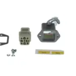
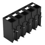
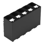
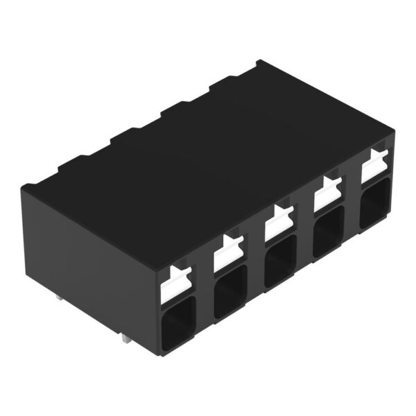
PCB terminal block, 2086 Series, push-buttonThis PCB terminal block (item number 2086-3205/300-000/997-607) is designed for simple and secure connections. It is a universal connector that can be used…
Request for Quote
Shipping & Delivery
-
 Courier delivery
Our courier will deliver to the specified address
5-6 Days
From €20
-
 DHL Courier delivery
DHL courier will deliver to the specified address
2-3 Days
From €40
-
 Warranty 1 year
-
 Free 30-Day returns
Description
PCB terminal block, 2086 Series, push-buttonThis PCB terminal block (item number 2086-3205/300-000/997-607) is designed for simple and secure connections. It is a universal connector that can be used almost anywhere, e.g., as a pluggable PCB connector, panel feedthrough header, connector for rail-mount terminal blocks, or a floating connector for different mounting methods. Ensure that the strip lengths are between 8 and 9 mm when connecting conductors to this PCB terminal block. This product features one conductor terminal and utilizes Push-in CAGE CLAMP®. Push-in CAGE CLAMP® connection technology is ideal for connecting all conductor types. It allows direct insertion of both solid and fine-stranded conductors with ferrules without the need for tools—all thanks to its pluggable design. The item’s dimensions are (24.2 x 9.3 x 13.6) mm (width x height x depth). This PCB terminal block is suitable for conductor cross sections ranging from 0.14 mm² to 1.5 mm².The contact surface is coated with tin. This PCB terminal block is operated with a push-button. The PCB terminal block is designed for THR soldering. Insert the conductor at a 0° angle..
Specification
Notes
| Note | Application notes:Suitable for lead-free, reflow-soldering profiles per DIN EN 61760-1 and IEC 60068-2-58 up to max. 260°C peak temperature. Due to application-specific variables (component configuration and orientation, type of soldering machine, solder paste), trial runs are recommended to ensure product and process compatibility under actual manufacturing conditions. |
|---|
Electrical data - Ratings per IEC/EN
| Ratings per | IEC/EN 60664-1 |
|---|---|
| Nominal voltage (III/3) | 320 V |
| Rated impulse withstand voltage (III / 3) | 4 kV |
| Rated voltage (III/2) | 320 V |
| Rated impulse withstand voltage (III/2) | 4 kV |
| Nominal voltage (II/2) | 630 V |
| Rated impulse withstand voltage (II/2) | 4 kV |
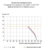
| Rated current | 17.5 A |
| Legend (ratings) | (III / 2) ≙ Overvoltage category III / Pollution degree 2 |
| Ratings per | IEC/EN 60664-1 / IEC/EN 60664-1 / IEC/EN 60664-1 |
| Overvoltage category | III / III / II |
| Pollution degree | 3 / 2 / 2 |
| Nominal voltage | 320 V / 320 V / 630 V |
| Rated impulse withstand voltage | 4 kV / 4 kV / 4 kV |
| Rated current | 17.5 A / 17.5 A / 17.5 A |
Electrical data - Ratings per UL
| Approvals per | UL 1059 |
|---|---|
| Rated voltage UL (Use Group B) | 300 V |
| Rated current UL (Use Group B) | 14 A |
| Rated voltage UL (Use Group D) | 300 V |
| Rated current UL (Use Group D) | 10 A |
| Approvals per | UL 1059 / UL 1059 / UL 1059 |
| Use group | B / C / D |
| Rated voltage | 300 V / 300 V |
| Rated current | 14 A / 10 A |
Electrical data - Ratings per CSA
| Approvals per | CSA |
|---|---|
| Rated voltage CSA (Use Group B) | 300 V |
| Rated current CSA (Use Group B) | 14 A |
| Rated voltage CSA (Use Group D) | 300 V |
| Rated current CSA (Use Group D) | 14 A |
| Approvals per | CSA / CSA / CSA |
| Use group | B / C / D |
| Rated voltage | 300 V / 300 V |
| Rated current | 14 A / 14 A |
Connection data
| Clamping units | 5 |
|---|---|
| Total number of potentials | 5 |
| Number of connection types | 1 |
| Number of levels | 1 |
Connection data - Connection 1
| Connection technology | Push-in CAGE CLAMP® |
|---|---|
| Actuation type | Push-button |
| Solid conductor | 0.14 … 1.5 mm² / 28 … 16 AWG |
| Fine-stranded conductor | 0.14 … 1.5 mm² / 26 … 14 AWG |
| Fine-stranded conductor; with insulated ferrule | 0.25 … 0.75 mm² |
| Fine-stranded conductor; with uninsulated ferrule | 0.25 … 1.5 mm² |
| Strip length | 8 … 9 mm / 0.31 … 0.35 inches |
| Conductor connection direction to PCB | 0 ° |
| Pole number | 5 |
Physical data
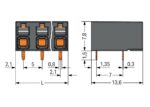
| Pin spacing | 5 mm / 0.197 inches |
|---|---|
| Width | 24.2 mm / 0.953 inches |
| Height | 9.3 mm / 0.366 inches |
| Height from the surface | 7.8 mm / 0.307 inches |
| Depth | 13.6 mm / 0.535 inches |
| Solder pin length | 1.5 mm |
| Solder pin dimensions | 0.3 x 0.8 mm |
| Plated through-hole diameter (THR) | 1 (+0.1) mm |
| Reel diameter of tape-and-reel packaging | 380 mm |
| Tape width | 56 mm |
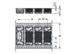
PCB contact
| PCB contact | THR |
|---|---|
| Solder pin arrangement | over the entire terminal strip (in-line) |
| Number of solder pins per potential | 2 |
Material data
| Note (material data) | Information on material specifications can be found here |
|---|---|
| Color | black |
| Material group | I |
| Insulation material (main housing) | Polyphthalamide (PPA GF) |
| Flammability class per UL94 | V0 |
| Clamping spring material | Chrome-nickel spring steel (CrNi) |
| Contact material | Electrolytic copper (ECu) |
| Contact plating | Tin |
| Fire load | 0.072 MJ |
| Weight | 3 g |
| MSL per J-STD 020D | 1 |
Environmental requirements
| Limit temperature range | -60 … +105 °C |
|---|---|
| Processing temperature | -35 … +60 °C |
| Continuous operating temperature | -60 … +105 °C |
Environmental requirements - Environmental Testing
| Test specification: <br/>Railway applications –<br/>Rolling stock –<br/>Electronic equipment | DIN EN 50155 (VDE 0115-200):2022-06 |
|---|---|
| Test procedure: <br/>Railway applications – <br/>Rolling stock equipment – <br/>Vibration and shock tests | DIN EN 61373 (VDE 0115-0106):2011-04 |
| Spectrum/Mounting location | Service life test, Category 1, Class A/B |
| Functional test with noise-like oscillations | Test passed according to Section 8 of the standard |
| Frequency | f1 = 5 Hz to f2 = 150 Hz |
| Acceleration | 0.101g (highest test level used for all axes) |
| Test duration per axis | 10 min. |
| Test directions | X, Y and Z axes |
| Monitoring of contact faults and interruptions | Passed |
| Voltage drop measurement before and after each axis | Passed |
| Simulated service life test through increased levels of noise-like oscillations | Test passed according to Section 9 of the standard |
| Frequency | f1 = 5 Hz to f2 = 150 Hz |
| Acceleration | 0.572g (highest test level used for all axes) |
| Test duration per axis | 5 h |
| Test directions | X, Y and Z axes |
| Extended testing: Monitoring of contact faults and interruptions | Passed |
| Extended testing: Voltage drop measurement before and after each axis | Passed |
| Shock test | Test passed according to Section 10 of the standard |
| Shock pulse form | Half sine |
| Acceleration | 5g (highest test level used for all axes) |
| Shock duration | 30 ms |
| Number of shocks (per axis) | 3 pos. und 3 neg. |
| Test directions | X, Y and Z axes |
| Extended testing: Monitoring of contact faults and interruptions | Passed |
| Extended testing: Voltage drop measurement before and after each axis | Passed |
| Vibration and shock stress for rolling stock equipment | Passed |
Commercial data
| PU (SPU) | 1660 (415) pcs |
|---|---|
| Packaging type | Box |
| Country of origin | CH |
| GTIN | 4066966459661 |
| Customs tariff number | 85369010000 |
Product Classification
| UNSPSC | 39121409 |
|---|---|
| ETIM 9.0 | EC002643 |
| ETIM 10.0 | EC002643 |
| ECCN | NO US CLASSIFICATION |
Environmental Product Compliance
| RoHS Compliance Status | Compliant,No Exemption |
|---|
Reviews
Clear filtersThere are no reviews yet.