


Fast delivery within 72 Hours
Wago 2086-1122/300-000/997-604
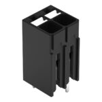
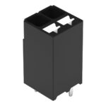
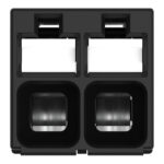
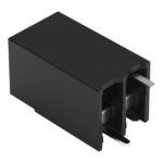
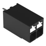
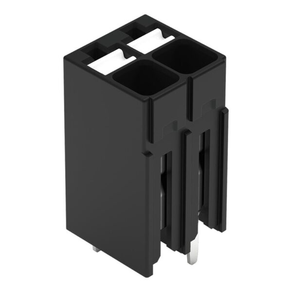
PCB terminal block, 2086 Series, Push-in CAGE CLAMP®Connect conductors quickly and easily with this PCB terminal block (item number 2086-1122/300-000/997-604). It offers the flexibility needed for dif…
Request for Quote
Shipping & Delivery
-
 Courier delivery
Our courier will deliver to the specified address
5-6 Days
From €20
-
 DHL Courier delivery
DHL courier will deliver to the specified address
2-3 Days
From €40
-
 Warranty 1 year
-
 Free 30-Day returns
Description
PCB terminal block, 2086 Series, Push-in CAGE CLAMP®Connect conductors quickly and easily with this PCB terminal block (item number 2086-1122/300-000/997-604). It offers the flexibility needed for different mounting types. Conductors should only be connected to this PCB terminal block if their strip length is between 8 and 9 mm . Featuring one conductor terminal along with Push-in CAGE CLAMP®, this connector outperforms the competition. Push-in CAGE CLAMP® technology provides a universal connection solution for all conductor types. It allows both solid and fine-stranded conductors with ferrules to be inserted directly into the clamping point without the need for tools. The item’s dimensions are (7.7 x 15.1 x 7.8) mm (width x height x depth). This PCB terminal block is suitable for conductor cross sections ranging from 0.14 mm² to 1.5 mm².Tin is used for coating the contact surfaces. A push-button is used to operate this PCB terminal block. THR is used to assemble the PCB terminal block. The conductor is designed to be inserted at an angle of 90°..
Specification
Notes
| Note | Application notes:Suitable for lead-free, reflow-soldering profiles per DIN EN 61760-1 and IEC 60068-2-58 up to max. 260°C peak temperature. Due to application-specific variables (component configuration and orientation, type of soldering machine, solder paste), trial runs are recommended to ensure product and process compatibility under actual manufacturing conditions., The mechanical stability of a two-pole terminal strip (2086 Series) with alternating pin spacing is lower than that of a multi-pole terminal strip with alternating pin spacing or a terminal strip with double pin spacing when subjected to external forces, owing to its design. It must be ensured that, in the application, additional support, temporary restraint of the connected conductors, and corresponding operating instructions protect the terminal strip from excessive mechanical stress, such as torsional or bending forces, both during conductor connection and in use. |
|---|
Electrical data - Ratings per IEC/EN
| Ratings per | IEC/EN 60664-1 |
|---|---|
| Nominal voltage (III/3) | 250 V |
| Rated impulse withstand voltage (III / 3) | 4 kV |
| Rated voltage (III/2) | 320 V |
| Rated impulse withstand voltage (III/2) | 4 kV |
| Nominal voltage (II/2) | 630 V |
| Rated impulse withstand voltage (II/2) | 4 kV |
| Rated current | 17.5 A |
| Legend (ratings) | (III / 2) ≙ Overvoltage category III / Pollution degree 2 |
| Ratings per | IEC/EN 60664-1 / IEC/EN 60664-1 / IEC/EN 60664-1 |
| Overvoltage category | III / III / II |
| Pollution degree | 3 / 2 / 2 |
| Nominal voltage | 250 V / 320 V / 630 V |
| Rated impulse withstand voltage | 4 kV / 4 kV / 4 kV |
| Rated current | 17.5 A / 17.5 A / 17.5 A |
Electrical data - Ratings per UL
| Approvals per | UL 1059 |
|---|---|
| Rated voltage UL (Use Group B) | 300 V |
| Rated current UL (Use Group B) | 14 A |
| Rated voltage UL (Use Group D) | 300 V |
| Rated current UL (Use Group D) | 10 A |
| Approvals per | UL 1059 / UL 1059 / UL 1059 |
| Use group | B / C / D |
| Rated voltage | 300 V / 300 V |
| Rated current | 14 A / 10 A |
Electrical data - Ratings per CSA
| Approvals per | CSA |
|---|---|
| Rated voltage CSA (Use Group B) | 300 V |
| Rated current CSA (Use Group B) | 14 A |
| Rated voltage CSA (Use Group D) | 300 V |
| Rated current CSA (Use Group D) | 14 A |
| Approvals per | CSA / CSA / CSA |
| Use group | B / C / D |
| Rated voltage | 300 V / 300 V |
| Rated current | 14 A / 14 A |
Connection data
| Clamping units | 2 |
|---|---|
| Total number of potentials | 2 |
| Number of connection types | 1 |
| Number of levels | 1 |
Connection data - Connection 1
| Connection technology | Push-in CAGE CLAMP® |
|---|---|
| Actuation type | Push-button |
| Solid conductor | 0.14 … 1.5 mm² / 28 … 16 AWG |
| Fine-stranded conductor | 0.14 … 1.5 mm² / 26 … 14 AWG |
| Fine-stranded conductor; with insulated ferrule | 0.25 … 0.75 mm² |
| Fine-stranded conductor; with uninsulated ferrule | 0.25 … 1.5 mm² |
| Strip length | 8 … 9 mm / 0.31 … 0.35 inches |
| Conductor connection direction to PCB | 90 ° |
| Pole number | 2 |
Physical data
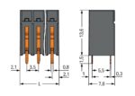
| Pin spacing | 3.5 mm / 0.138 inches |
|---|---|
| Width | 7.7 mm / 0.303 inches |
| Height | 15.1 mm / 0.594 inches |
| Height from the surface | 13.6 mm / 0.535 inches |
| Depth | 7.8 mm / 0.307 inches |
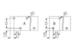
| Solder pin length | 1.5 mm |
| Solder pin dimensions | 0.3 x 0.8 mm |
| Plated through-hole diameter (THR) | 1 (+0.1) mm |
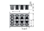
| Reel diameter of tape-and-reel packaging | 380 mm |
| Tape width | 24 mm |
PCB contact
| PCB contact | THR |
|---|---|
| Solder pin arrangement | over the entire terminal strip (staggered) |
| Number of solder pins per potential | 1 |
Material data
| Note (material data) | Information on material specifications can be found here |
|---|---|
| Color | black |
| Material group | I |
| Insulation material (main housing) | Polyphthalamide (PPA GF) |
| Flammability class per UL94 | V0 |
| Clamping spring material | Chrome-nickel spring steel (CrNi) |
| Contact material | Electrolytic copper (ECu) |
| Contact plating | Tin |
| Fire load | 0.028 MJ |
| Weight | 1 g |
| MSL per J-STD 020D | 1 |
Environmental requirements
| Limit temperature range | -60 … +105 °C |
|---|---|
| Processing temperature | -35 … +60 °C |
| Continuous operating temperature | -60 … +105 °C |
Environmental requirements - Environmental Testing
| Test specification: <br/>Railway applications –<br/>Rolling stock –<br/>Electronic equipment | DIN EN 50155 (VDE 0115-200):2022-06 |
|---|---|
| Test procedure: <br/>Railway applications – <br/>Rolling stock equipment – <br/>Vibration and shock tests | DIN EN 61373 (VDE 0115-0106):2011-04 |
| Spectrum/Mounting location | Service life test, Category 1, Class A/B |
| Functional test with noise-like oscillations | Test passed according to Section 8 of the standard |
| Frequency | f1 = 5 Hz to f2 = 150 Hz |
| Acceleration | 0.101g (highest test level used for all axes) |
| Test duration per axis | 10 min. |
| Test directions | X, Y and Z axes |
| Monitoring of contact faults and interruptions | Passed |
| Voltage drop measurement before and after each axis | Passed |
| Simulated service life test through increased levels of noise-like oscillations | Test passed according to Section 9 of the standard |
| Frequency | f1 = 5 Hz to f2 = 150 Hz |
| Acceleration | 0.572g (highest test level used for all axes) |
| Test duration per axis | 5 h |
| Test directions | X, Y and Z axes |
| Extended testing: Monitoring of contact faults and interruptions | Passed |
| Extended testing: Voltage drop measurement before and after each axis | Passed |
| Shock test | Test passed according to Section 10 of the standard |
| Shock pulse form | Half sine |
| Acceleration | 5g (highest test level used for all axes) |
| Shock duration | 30 ms |
| Number of shocks (per axis) | 3 pos. und 3 neg. |
| Test directions | X, Y and Z axes |
| Extended testing: Monitoring of contact faults and interruptions | Passed |
| Extended testing: Voltage drop measurement before and after each axis | Passed |
| Vibration and shock stress for rolling stock equipment | Passed |
Commercial data
| PU (SPU) | 2115 (235) pcs |
|---|---|
| Packaging type | Box |
| Country of origin | CH |
| GTIN | 4066966459883 |
| Customs tariff number | 85369010000 |
Product Classification
| UNSPSC | 39121409 |
|---|---|
| ETIM 9.0 | EC002643 |
| ETIM 10.0 | EC002643 |
| ECCN | NO US CLASSIFICATION |
Environmental Product Compliance
| RoHS Compliance Status | Compliant,No Exemption |
|---|
Reviews
Clear filtersThere are no reviews yet.