


Fast delivery within 72 Hours
Wago 2059-323/998-403
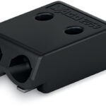
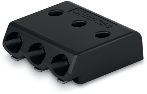
PCB terminal block, 2059 Series, blackEasily, quickly and safely connect conductors with this PCB terminal block (item number 2059-323/998-403). You can count on trusted safety with these PCB terminal…
Request for Quote
Shipping & Delivery
-
 Courier delivery
Our courier will deliver to the specified address
5-6 Days
From €20
-
 DHL Courier delivery
DHL courier will deliver to the specified address
2-3 Days
From €40
-
 Warranty 1 year
-
 Free 30-Day returns
Description
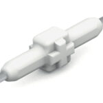
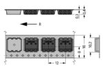
PCB terminal block, 2059 Series, blackEasily, quickly and safely connect conductors with this PCB terminal block (item number 2059-323/998-403). You can count on trusted safety with these PCB terminal blocks, perfect for a wide range of applications when designing your devices. Strip lengths must be between 4 and 5.5 mm when connecting conductors to this PCB terminal block. This product features one conductor terminal and utilizes PUSH WIRE®. Our PUSH WIRE® connection uses the stiffness of the conductor to overcome the clamping spring’s contact force, allowing you to clamp the conductor in place more quickly and easily. The item’s dimensions are (8.9 x 2.7 x 7.9) mm (width x height x depth). This PCB terminal block is suitable for conductor cross sections ranging from 0.14 mm² to 0.34 mm² on one side and for conductor cross sections ranging from 0.5 mm² to 0.5 mm² on the other side.The contact surface is coated with tin. An operating tool is used to operate this PCB terminal block. SMD is used to assemble the PCB terminal block. Insert the conductor into the board at an angle of 0°..The 2059 Series SMD PCB Terminal Block is the smallest 2.7 mm terminal block with an insulated plastic housing in the portfolio. The white housing is perfect for use in LED lights and provides minimal shadowing thanks to its small design with rounded corners. WAGO’s 2059 Series design is accented by a clean look and characteristic round hole for the operating tool for disconnecting conductors. Thanks to the slim design, terminal blocks can be arranged side-by-side without pole loss and without limitation. The slightly slanted shape of the terminal block front with the balcony-like projection of the underside not only allows a good view from above of the conductor entry hole, it also enables quick and easy insertion of solid conductors.
Specification
Notes
| Note | Application notes:Suitable for lead-free, reflow-soldering profiles per DIN EN 61760-1 and IEC 60068-2-58 up to max. 260°C peak temperature. Due to application-specific variables (component configuration and orientation, type of soldering machine, solder paste), trial runs are recommended to ensure product and process compatibility under actual manufacturing conditions., Depending on reflow soldering temperatures and times, color deviations may occur. These deviations will have no impact on functionality. |
|---|---|
| Recommendation | Recommendation for stencil:150 µm material thickness; Pattern layout identical to solder pad layout |
Electrical data - Ratings per IEC/EN
| Ratings per | IEC/EN 60664-1 |
|---|---|
| Nominal voltage (III/3) | 63 V |
| Rated impulse withstand voltage (III / 3) | 2.5 kV |
| Rated voltage (III/2) | 160 V |
| Rated impulse withstand voltage (III/2) | 2.5 kV |
| Nominal voltage (II/2) | 320 V |
| Rated impulse withstand voltage (II/2) | 2.5 kV |
| Rated current | 3 A |
| Legend (ratings) | (III / 2) ≙ Overvoltage category III / Pollution degree 2 |
| Ratings per | IEC/EN 60664-1 / IEC/EN 60664-1 / IEC/EN 60664-1 |
| Overvoltage category | III / III / II |
| Pollution degree | 3 / 2 / 2 |
| Nominal voltage | 63 V / 160 V / 320 V |
| Rated impulse withstand voltage | 2.5 kV / 2.5 kV / 2.5 kV |
| Rated current | 3 A / 3 A / 3 A |
Electrical data - Ratings per UL 1977
| Rated voltage (UL 1977) | 250 V |
|---|---|
| Rated current UL 1977 | 3 A |
| Approvals per | UL 1977 |
| Rated voltage | 250 V |
| Rated current | 3 A |
Connection data
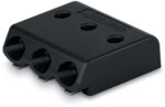
| Clamping units | 3 |
|---|---|
| Total number of potentials | 3 |
| Number of connection types | 1 |
| Number of levels | 1 |
Connection data - Connection 1
| Connection technology | PUSH WIRE® |
|---|---|
| Actuation type | Operating tool |
| Solid conductor | 0.14 … 0.34 mm² / 26 … 22 AWG |
| Note (conductor cross-section) | For conductors (26 AWG) that are not rigid enough, the clamping unit must be opened using an operating tool. |
| Strip length | 4 … 5.5 mm / 0.16 … 0.22 inches |
| Conductor connection direction to PCB | 0 ° |
| Pole number | 3 |
Connection data - Connection 2
| Solid conductor | 0.5 mm² / 20 AWG |
|---|---|
| Note (conductor cross-section) | No reconnection of smaller conductor cross-sections (0.5 mm²/20 AWG) |
| Strip length | 6 … 7.5 mm / 0.24 … 0.3 inches |
Physical data
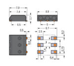
| Pin spacing | 3 mm / 0.118 inches |
|---|---|
| Width | 8.9 mm / 0.35 inches |
| Height | 2.7 mm / 0.106 inches |
| Depth | 7.9 mm / 0.311 inches |
| Reel diameter of tape-and-reel packaging | 330 mm |
| Tape width | 16 mm |
PCB contact
| PCB contact | SMD |
|---|---|
| Solder pin arrangement | Over the entire terminal strip (in-line) |
| Number of solder pins per potential | 2 |
Material data
| Note (material data) | Information on material specifications can be found here |
|---|---|
| Color | black |
| Material group | I |
| Insulation material (main housing) | Polyphthalamide (PPA GF) |
| Flammability class per UL94 | V0 |
| Contact material | Copper alloy |
| Contact plating | Tin |
| Fire load | 0.004 MJ |
| Weight | 0.2 g |
Environmental requirements
| Limit temperature range | -60 … +105 °C |
|---|
Environmental requirements - Environmental Testing
| Test specification: <br/>Railway applications –<br/>Rolling stock –<br/>Electronic equipment | DIN EN 50155 (VDE 0115-200):2022-06 |
|---|---|
| Test procedure: <br/>Railway applications – <br/>Rolling stock equipment – <br/>Vibration and shock tests | DIN EN 61373 (VDE 0115-0106):2011-04 |
| Spectrum/Mounting location | Service life test, Category 1, Class A/B |
| Functional test with noise-like oscillations | Test passed according to Section 8 of the standard |
| Frequency | f1 = 5 Hz to f2 = 150 Hz |
| Acceleration | 0.101g (highest test level used for all axes) |
| Test duration per axis | 10 min. |
| Test directions | X, Y and Z axes |
| Monitoring of contact faults and interruptions | Passed |
| Voltage drop measurement before and after each axis | Passed |
| Simulated service life test through increased levels of noise-like oscillations | Test passed according to Section 9 of the standard |
| Frequency | f1 = 5 Hz to f2 = 150 Hz |
| Acceleration | 0.572g (highest test level used for all axes) |
| Test duration per axis | 5 h |
| Test directions | X, Y and Z axes |
| Extended testing: Monitoring of contact faults and interruptions | Passed |
| Extended testing: Voltage drop measurement before and after each axis | Passed |
| Shock test | Test passed according to Section 10 of the standard |
| Shock pulse form | Half sine |
| Acceleration | 5g (highest test level used for all axes) |
| Shock duration | 30 ms |
| Number of shocks (per axis) | 3 pos. und 3 neg. |
| Test directions | X, Y and Z axes |
| Extended testing: Monitoring of contact faults and interruptions | Passed |
| Extended testing: Voltage drop measurement before and after each axis | Passed |
| Vibration and shock stress for rolling stock equipment | Passed |
Commercial data
| PU (SPU) | 21000 (1750) pcs |
|---|---|
| Packaging type | box |
| Country of origin | CH |
| GTIN | 4055143476515 |
| Customs tariff number | 85369010000 |
Product Classification
| UNSPSC | 39121409 |
|---|---|
| eCl@ss 10.0 | 27-14-11-06 |
| eCl@ss 9.0 | 27-14-11-06 |
| ETIM 9.0 | EC001284 |
| ETIM 10.0 | EC001284 |
| ECCN | NO US CLASSIFICATION |
Environmental Product Compliance
| RoHS Compliance Status | Compliant,No Exemption |
|---|
Reviews
Clear filtersThere are no reviews yet.