


Fast delivery within 72 Hours
Wago 2004-1211/1000-401
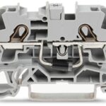
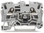
Component terminal block with diode, 2004 Series, Push-in CAGE CLAMP®Connect conductors quickly and securely with this component terminal block with diode (item number 2004-1211/1000-401). Strip lengt…
Request for Quote
Shipping & Delivery
-
 Courier delivery
Our courier will deliver to the specified address
5-6 Days
From €20
-
 DHL Courier delivery
DHL courier will deliver to the specified address
2-3 Days
From €40
-
 Warranty 1 year
-
 Free 30-Day returns
Description
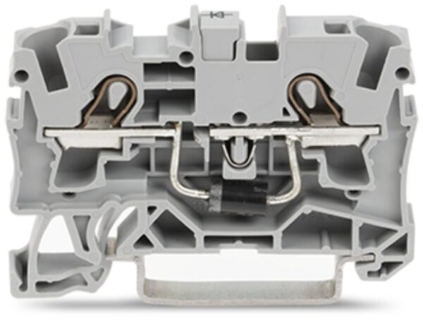
Component terminal block with diode, 2004 Series, Push-in CAGE CLAMP®Connect conductors quickly and securely with this component terminal block with diode (item number 2004-1211/1000-401). Strip lengths must be between 11 and 13 mm when connecting conductors to this component terminal block with diode. This product features conductor terminals and utilizes Push-in CAGE CLAMP®. Our Push-in CAGE CLAMP® is a universal, maintenance-free connection solution for all conductor types, offering a key advantage: It allows direct insertion of both solid and fine-stranded conductors with ferrules without needing tools. No preparation is required; for example, crimping the conductor’s ferrule is not necessary. This component terminal block with diode is suitable for conductor cross sections ranging from 0.5 mm² to 6 mm².
Specification
Electrical data - General information
| Nominal voltage | 250 V |
|---|---|
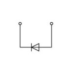
| Reverse voltage | 1,000 V |
| Continuous current (max.) | 1.5 A |
| Number/type of diode/LED | with 1N5408 diode |
| Wiring direction | Front-entry wiring |
Connection data
| Clamping units | 2 |
|---|---|
| Total number of potentials | 1 |
| Number of levels | 1 |
Connection data - Connection 1
| Connection technology | Push-in CAGE CLAMP® |
|---|---|
| Actuation type | Operating tool |
| Connectable conductor materials | Copper |
| Nominal cross-section | 4 mm² |
| Solid conductor | 0.5 … 6 mm² / 20 … 10 AWG |
| Solid conductor; push-in termination | 1.5 … 6 mm² / 14 … 10 AWG |
| Fine-stranded conductor | 0.5 … 6 mm² / 20 … 10 AWG |
| Fine-stranded conductor; with insulated ferrule | 0.5 … 4 mm² / 20 … 12 AWG |
| Fine-stranded conductor; with ferrule; push-in termination | 1.5 … 4 mm² / 18 … 12 AWG |
| Note (conductor cross-section) | Depending on the conductor characteristic, a conductor with a smaller cross-section can also be inserted via push-in termination. |
| Strip length | 11 … 13 mm / 0.43 … 0.51 inches |
| Wiring direction | Front-entry wiring |
Physical data
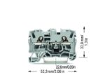
| Width | 6.2 mm / 0.244 inches |
|---|---|
| Height | 52.3 mm / 2.059 inches |
| Depth from upper-edge of DIN-rail | 32.9 mm / 1.295 inches |
Mechanical data
| Mounting type | DIN-35 rail |
|---|---|
| Marking level | Center/side marking |
Material data
| Note (material data) | Information on material specifications can be found here |
|---|---|
| Color | gray |
| Material group | I |
| Insulation material (main housing) | Polyamide (PA66) |
| Flammability class per UL94 | V0 |
| Fire load | 0.142 MJ |
| Weight | 8.3 g |
Environmental requirements
| Processing temperature | -35 … +85 °C |
|---|---|
| Continuous operating temperature | -60 … +105 °C |
Environmental requirements - Environmental Testing
| Test specification: <br/>Railway applications –<br/>Rolling stock –<br/>Electronic equipment | DIN EN 50155 (VDE 0115-200):2022-06 |
|---|---|
| Test procedure: <br/>Railway applications – <br/>Rolling stock equipment – <br/>Vibration and shock tests | DIN EN 61373 (VDE 0115-0106):2011-04 |
| Spectrum/Mounting location | Service life test, Category 1, Class A/B |
| Functional test with noise-like oscillations | Test passed according to Section 8 of the standard |
| Frequency | f1 = 5 Hz to f2 = 150 Hz |
| Acceleration | 0.101g (highest test level used for all axes) |
| Test duration per axis | 10 min. |
| Test directions | X, Y and Z axes |
| Monitoring of contact faults and interruptions | Passed |
| Voltage drop measurement before and after each axis | Passed |
| Simulated service life test through increased levels of noise-like oscillations | Test passed according to Section 9 of the standard |
| Frequency | f1 = 5 Hz to f2 = 150 Hz |
| Acceleration | 0.572g (highest test level used for all axes) |
| Test duration per axis | 5 h |
| Test directions | X, Y and Z axes |
| Extended testing: Monitoring of contact faults and interruptions | Passed |
| Extended testing: Voltage drop measurement before and after each axis | Passed |
| Shock test | Test passed according to Section 10 of the standard |
| Shock pulse form | Half sine |
| Acceleration | 5g (highest test level used for all axes) |
| Shock duration | 30 ms |
| Number of shocks (per axis) | 3 pos. und 3 neg. |
| Test directions | X, Y and Z axes |
| Extended testing: Monitoring of contact faults and interruptions | Passed |
| Extended testing: Voltage drop measurement before and after each axis | Passed |
| Vibration and shock stress for rolling stock equipment | Passed |
Commercial data
| Product Group | 22 (TOPJOB S) |
|---|---|
| PU (SPU) | 50 pcs |
| Packaging type | box |
| Country of origin | DE |
| GTIN | 4050821230953 |
| Customs tariff number | 85369010000 |
Product Classification
| UNSPSC | 39121410 |
|---|---|
| eCl@ss 10.0 | 27-14-11-27 |
| eCl@ss 9.0 | 27-14-11-27 |
| ETIM 9.0 | EC000903 |
| ETIM 10.0 | EC000903 |
| ECCN | NO US CLASSIFICATION |
Environmental Product Compliance
| RoHS Compliance Status | Compliant,No Exemption |
|---|---|
| SCIP notification number (Austria) | 12874ec2-c7e9-4fe8-8bd2-76ed484bcb6e |
| SCIP notification number (Belgium) | ab190a89-d7a7-40ef-b602-594a402e2890 |
| SCIP notification number (Bulgaria) | 58069aeb-6d46-4b49-b252-cb07deabf5c1 |
| SCIP notification number (Czech Republic) | b07fc5ca-62ea-461a-bad0-4e8cc24141ee |
| SCIP notification number (Denmark) | 74dade8d-ff2e-4202-b3c5-c1754841c98c |
| SCIP notification number (Finland) | 60e42887-e407-4027-98ab-ee25975d66ce |
| SCIP notification number (France) | 3e589af5-24a9-4537-b3f0-d6c681daeccd |
| SCIP notification number (Germany) | cbb87f3c-5b21-4352-973b-01fb0261c247 |
| SCIP notification number (Hungary) | 7f2dc519-f2fe-4f2e-9613-20ea2d5319b8 |
| SCIP notification number (Italy) | 022bba25-4d3e-4ccb-ba49-1903b1da4403 |
| SCIP notification number (Netherlands) | ed14c838-92c7-4ad6-9b95-8dfc7dfaab50 |
| SCIP notification number (Poland) | b8ae8649-5574-4431-afab-e952fc490b2c |
| SCIP notification number (Romania) | df57adfc-d8ed-4171-b1e6-8f53903d74b3 |
| SCIP notification number (Sweden) | 4d94d997-4154-43a8-b87b-ab04509ffbe4 |
Reviews
Clear filtersThere are no reviews yet.