")
Fast delivery within 72 Hours
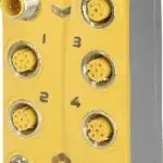
B&R X67SM2436
€ 571,34
5 in stock
2 stepper motors, 24 to 38.5 VDC ±25%, 3 A (5 A peak)Current value resolution of 1%Boost, nominal and holding current separately configurable38.5 kHz PWM frequencyIntegrated motor detection256 microst…
5 in stock
Request for Quote
Shipping & Delivery
-
 Courier delivery
Our courier will deliver to the specified address
5-6 Days
From €20
-
 DHL Courier delivery
DHL courier will deliver to the specified address
2-3 Days
From €40
-
 Warranty 1 year
-
 Free 30-Day returns
Description
2 stepper motors, 24 to 38.5 VDC ±25%, 3 A (5 A peak)Current value resolution of 1%Boost, nominal and holding current separately configurable38.5 kHz PWM frequencyIntegrated motor detection256 microstepsStall detectionComplete integration in Automation Studio and CNC applications2x 3 inputs, 24 VDC, configurable for ABR incremental encodersIntegrated short-circuit proof encoder power supplyFunction model 3 (“Ramp”) based on CANopen communication profile DS402NetTime timestamp: Position change, trigger time
The stepper motor module is used to control up to 2 stepper motors with a nominal voltage of 24 to 38.5 VDC ±25% at a motor current up to 3 A (5 A peak).In addition, this module has 6 digital inputs that can be used as limit switches or encoder inputs.Due to the individual adjustment of the coil currents, the motor is only operated with the current it actually needs. This simplifies the selection of the available motors and prevents unnecessary heating. Because this affects energy consumption and thermal load, the effects are positive on the service life of the complete system. Complete flexibility is achieved through the use of independently adjustable holding, boost and nominal current values. The current for microsteps is automatically adjusted to the configured current values.The automatic motor identification system is an enormous help during standstills. The stepper motor modules can identify the connected motors using their coil characteristics and generate feedback in the form of an analog value. This makes it possible to detect not only wiring errors, but also incorrect motor types being used mistakenly. A stall detection mechanism is integrated to analyze the motor load. Detection of the stall is defined via a configurable threshold. This allows an overload or motor standstill to be detected precisely in many different types of applications.
Specification
| I/O module |
2 full bridges for controlling stepper motors |
|---|---|
| B&R ID code |
0x1DCB |
| Status indicators |
I/O function per channel, supply voltage, bus function |
| I/O power supply |
M8, 4-pin |
| Motor status |
Yes, using LED status indicator and software |
| X2X Link |
M12, B-coded |
| Inputs/Outputs |
4x M12, A-coded |
| X2X Link power supply |
0.75 W |
| At 24 VDC |
1.7 W |
| At 48 VDC |
2 W |
| CE |
Yes |
| UKCA |
Yes |
| CRA (Cyber Resilience Act) |
In preparation |
| ATEX |
Zone 2, II 3G Ex nA IIA T5 Gc |
| UL |
cULus E115267 |
| HazLoc |
cCSAus 244665 |
| KC |
Yes |
| Quantity |
2 |
| Type |
2-phase bipolar stepper motor (full bridge) |
| Nominal voltage |
24 VDC |
| Nominal current |
3 A |
| Max. current/motor |
5 A for 2 s (after a recovery time of at least 10 s at maximum 3 A) |
| Max. current/module |
8 A |
| Controller frequency |
38.5 kHz |
| DC bus capacitance |
200 µF |
| Step resolution |
256 microsteps per full step |
| Sensor power supply |
Max. 0.96 W |
| Reverse polarity protection |
No |
| Input characteristics per EN 61131-2 |
Type 1 |
| Input voltage |
24 VDC -15% / +20% |
| Input current at 24 VDC |
Approx. 4 mA |
| Input circuit |
Sink |
| Hardware |
<5 µs |
| Software |
– |
| Input resistance |
Typ. 5.4 kΩ |
| Additional functions |
2x ABR incremental encoder |
| Low |
<5 VDC |
| High |
>15 VDC |
| Insulation voltage between channel and bus |
500 Veff |
| Encoder inputs |
24 V, asymmetrical |
| Counter size |
16-bit |
| Input frequency |
Max. 50 kHz |
| Evaluation |
4x |
| Encoder power supply |
Module-internal, max. 20 mA per encoder |
| Signal form |
Square wave pulse |
| Counter 1 |
Inputs 1 to 3 |
| Counter 2 |
Inputs 4 to 6 |
| Counter frequency |
Max. 200 kHz |
| Supply voltage |
24 VDC |
| Short-circuit proof |
Yes |
| Min. voltage at 20 mA / group |
20 VDC |
| Electrical isolation |
Channel isolated from bus |
| Any |
Yes |
| 0 to 2000 m |
No limitation |
| >2000 m |
Reduction of ambient temperature by 0.5°C per 100 m |
| Degree of protection per EN 60529 |
IP67 |
| Operation |
0 to 50°C |
| Derating |
– |
| Storage |
-25 to 85°C |
| Transport |
-25 to 85°C |
| Width |
53 mm |
| Height |
85 mm |
| Depth |
42 mm |
| Weight |
195 g |
| M8 |
Max. 0.4 Nm |
| M12 |
Max. 0.6 Nm |
Reviews
Clear filtersThere are no reviews yet.