")
Fast delivery within 72 Hours
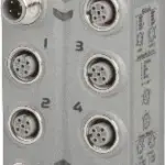
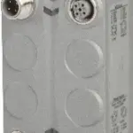
B&R X67MM2436
2x outputs (H bridge) with PWM control and 24 to 38.5 VDC ±25% supply3 A rated current (5 A max current)15 Hz to 50 kHz frequency, 16-bitPWM resolution, 15-bit, + sign, minimum 10 nsConfigurable dithe…
Request for Quote
Shipping & Delivery
-
 Courier delivery
Our courier will deliver to the specified address
5-6 Days
From €20
-
 DHL Courier delivery
DHL courier will deliver to the specified address
2-3 Days
From €40
-
 Warranty 1 year
-
 Free 30-Day returns
Description
2x outputs (H bridge) with PWM control and 24 to 38.5 VDC ±25% supply3 A rated current (5 A max current)15 Hz to 50 kHz frequency, 16-bitPWM resolution, 15-bit, + sign, minimum 10 nsConfigurable dither2x 3 inputs 24 V, can be configured as ABRSink connectionIntegrated sensor supply with short circuit protection1-wire connections24 VDC and GND for encoder supply
This motor bridge module is used to control 2 DC motors with a nominal voltage of 24 to 38.5 VDC ±25% at a nominal current up to 3 A. The module can be reconfigured and used in current controller mode for controlling inductive loads. The module is also equipped with 6 digital inputs, which can be used as incremental counters. Each motor is controlled with a full-bridge (H-bridge). This enables the motors to be moved in both directions.
Specification
| I/O module | 2-channel PWM output (H bridge) 2x 3 inputs for ABR incremental encoder |
|---|---|
| B&R ID code | 0x2273 |
| Sensor power supply | Max. 1 W |
| Output | Per channel |
| Input | Per group (3 inputs) |
| Other | Supply voltage, bus function |
| Outputs | Yes, open circuit via software status |
| I/O power supply | M8, 4-pin |
| X2X Link | M12, B-coded |
| Inputs/Outputs | 4x M12, A-coded |
| Internal I/O | 1 W |
| X2X Link power supply | 0.75 W |
| CE | Yes |
| UKCA | Yes |
| CRA (Cyber Resilience Act) | In preparation |
| ATEX | Zone 2, II 3G Ex nA IIA T5 Gc IP67, Ta = 0 – Max. 60°C TÜV 05 ATEX 7201X |
| UL | cULus E115267 Industrial control equipment |
| HazLoc | cCSAus 244665 Process control equipment for hazardous locations Class I, Division 2, Groups ABCD, T5 |
| KC | Yes |
| Nominal voltage | 24 to 38.5 VDC ±25% |
| Reverse polarity protection | No |
| Quantity | 2 |
| Input characteristics per EN 61131-2 | Type 1 |
| Input voltage | 24 VDC (-15%/+20%) |
| Input current at 24 VDC | Approx. 4 mA |
| Input circuit | Sink |
| Hardware | <5 µs |
| Software | – |
| Input resistance | Typ. 5.4 kΩ |
| Additional functions | 2x ABR incremental encoder (+24 VDC), 2x AB incremental encoder, 2x event counter, 2x period duration / gate measurement |
| Low | <5 VDC |
| High | >15 VDC |
| Insulation voltage between channel and bus | 500 Veff |
| Encoder inputs | 24 VDC, asymmetrical |
| Counter size | 16-bit |
| Input frequency | Max. 50 kHz |
| Evaluation | 4x |
| Encoder power supply | Module-internal, max. 20 mA per encoder |
| Signal form | Square wave pulse |
| Counter 1 | Inputs 1 to 3 |
| Counter 2 | Inputs 4 to 6 |
| Counter frequency | Max. 200 kHz |
| Supply voltage | 24 VDC |
| Short-circuit proof | Yes |
| Min. voltage at 20 mA / group | 20 VDC |
| Type | H bridge |
| PWM frequency | 15 Hz to 50 kHz |
| Variant | H bridge |
| Configurable dither | Amplitude, frequency |
| Period duration resolution | 16-bit, min. 20 μs |
| Phase shift PWM1 to PWM2 | 180° |
| DC bus capacitance | 200 µF |
| Nominal current | 3 A |
| Max. current/output | 5 A for 2 s (after a recovery time of at least 10 s at maximum 3 A) |
| Max. current/module | 8 A |
| PWM mode | 15 bits plus sign ≥10 ns |
| Current mode | 15 bits plus sign ≥10 ns |
| Electrical isolation | Channel isolated from bus Channel not isolated from channel |
| Any | Yes |
| 0 to 2000 m | No limitation |
| >2000 m | Reduction of ambient temperature by 0.5°C per 100 m |
| Degree of protection per EN 60529 | IP67 |
| Operation | -25 to 55°C |
| Derating | – |
| Storage | -40 to 85°C |
| Transport | -40 to 85°C |
| Width | 53 mm |
| Height | 85 mm |
| Depth | 42 mm |
| Weight | 225 g |
| M8 | Max. 0.4 Nm |
| M12 | Max. 0.6 Nm |
Reviews
Clear filtersThere are no reviews yet.