")
Fast delivery within 72 Hours
B&R X67DC1198
2 incremental or SSI encoder inputs 5 V2 digital channels, 24 V per connection, configurable either as inputs or outputs4 AB counters on the digital inputsPulse width modulation of the digital outputs…
Request for Quote
Shipping & Delivery
-
 Courier delivery
Our courier will deliver to the specified address
5-6 Days
From €20
-
 DHL Courier delivery
DHL courier will deliver to the specified address
2-3 Days
From €40
-
 Warranty 1 year
-
 Free 30-Day returns
Description
2 incremental or SSI encoder inputs 5 V2 digital channels, 24 V per connection, configurable either as inputs or outputs4 AB counters on the digital inputsPulse width modulation of the digital outputsEncoder power supply 5 V and 24 V integrated in encoder connection
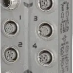
The possibilities are almost endless with this digital counter module. Connectors 1 and 3 are 12-pin M12 connectors. Each of these can be used to connect 1 incremental encoder or SSI encoder with 5 V differential signals. In addition, there are 2 digital channels available on the same output which, when configured as inputs, can be used with incremental encoders with status outputs (e.g. alarms). When configured as outputs, they act as preset and count direction switching functions when used together with SSI encoders, for example.2 more sockets and 2 more configurable digital channels are available on female connectors 2 and 4. The inputs can be used as latch, gate, or home enable switches, while the outputs can be used as comparator outputs, for example.
Specification
| I/O module |
2 SSI absolute encoders 5 V or 2 ABR incremental encoders 5 V, |
|---|---|
| Insulation voltage between encoder and bus |
500 Veff |
| B&R ID code |
0x18D0 |
| Sensor/Actuator power supply |
Max. 12 W |
| Status indicators |
I/O function per channel, supply voltage, bus function |
| Outputs |
Yes, using LED status indicator and software |
| I/O power supply |
M8, 4-pin |
| X2X Link |
M12, B-coded |
| Inputs/Outputs |
2x M12, 5-pin, A-coded |
| SSI/ABR encoder |
2x M12, 12-pin, A-coded |
| Internal I/O |
2.8 W |
| X2X Link power supply |
0.75 W |
| CE |
Yes |
| UKCA |
Yes |
| CRA (Cyber Resilience Act) |
In preparation |
| ATEX |
Zone 2, II 3G Ex nA IIA T5 Gc |
| UL |
cULus E115267 |
| HazLoc |
cCSAus 244665 |
| KC |
Yes |
| Nominal voltage |
24 VDC |
| Voltage range |
18 to 30 VDC |
| Integrated protective function |
Reverse polarity protection |
| Voltage |
I/O power supply minus voltage drop for short-circuit protection |
| Voltage drop for short-circuit protection at 0.5 A |
Max. 2 VDC |
| Summation current |
Max. 0.5 A |
| Short-circuit proof |
Yes |
| Quantity |
Up to 8, configuration as input or output using software |
| Encoder inputs |
24 V, asymmetrical |
| Counter size |
16-bit |
| Max. transfer rate |
1 Mbit/s |
| Coding |
Gray/Binary |
| Overload characteristics of encoder power supply |
Short-circuit proof, overload-proof |
| Transfer rate |
125 kbit/s, 250 kbit/s, 500 kbit/s, 1 Mbit/s |
| 5 VDC |
Module-internal, max. 0.3 A summation current |
| 24 VDC |
Module-internal, max. 0.5 A summation current |
| Input frequency |
Max. 100 kHz |
| Evaluation |
2x |
| Hardware |
≤2 µs |
| Software |
– |
| Common-mode range |
-7 V ≤ VCM ≤ +12 V |
| Encoder power supply 24 VDC |
Module-internal, max. 0.5 A summation current |
| Input characteristics per EN 61131-2 |
Type 1 |
| Additional functions |
Pulse width modulation, comparator function |
| Input circuit |
Sink |
| Input voltage |
18 to 30 VDC |
| Input current at 24 VDC |
Approx. 3.3 mA |
| Input resistance |
7.31 kΩ |
| Low |
<5 VDC |
| High |
>15 VDC |
| Possible measurements |
Gate time, period duration, edge offset for various channels |
| Measurements per module |
Up to 9 |
| Measurements per channel |
Up to 2 |
| Signal form |
Square wave pulse |
| Internal |
8 MHz, 4 MHz, 2 MHz, 1 MHz, 500 kHz, 250 kHz, 125 kHz, 62.5 kHz |
| Measurement type |
Continuous or triggered |
| Type |
5 VDC differential signal, EiA RS485 standard |
| Output circuit |
Sink or source |
| Output protection |
Thermal shutdown in the event of overcurrent or short circuit, integrated protection for switching inductive loads, reverse polarity protection of the output power supply |
| Variant |
Push / Pull / Push-Pull |
| Diagnostic status |
Output monitoring |
| Nominal output current |
0.1 A |
| Total nominal current |
0.8 A |
| Braking voltage when switching off inductive loads |
Switching voltage + 0.6 VDC |
| Switch-on in the event of overload shutdown or short-circuit shutdown |
Approx. 10 ms (depends on the module temperature) |
| Peak short-circuit current |
<10 A |
| Leakage current when the output is switched off |
Max. 25 µA |
| Residual voltage |
<0.9 V at 0.1 A nominal current |
| Switching voltage |
I/O power supply minus residual voltage |
| Period duration |
41.6 µs to 500 ms |
| Pulse duration |
0 to 100% |
| Resolution |
0.1% |
| Resistive load |
Max. 24 kHz |
| 0 → 1 |
<2 µs |
| 1 → 0 |
<2 µs |
| Electrical isolation |
Bus isolated from encoder and channel Channel not isolated from channel and encoder Encoder not isolated from encoder |
| Any |
Yes |
| 0 to 2000 m |
No limitation |
| >2000 m |
Reduction of ambient temperature by 0.5°C per 100 m |
| Degree of protection per EN 60529 |
IP67 |
| Operation |
-25 to 60°C |
| Derating |
– |
| Storage |
-40 to 85°C |
| Transport |
-40 to 85°C |
| Width |
53 mm |
| Height |
85 mm |
| Depth |
42 mm |
| Weight |
200 g |
| M8 |
Max. 0.4 Nm |
| M12 |
Max. 0.6 Nm |
Reviews
Clear filtersThere are no reviews yet.