")
Fast delivery within 72 Hours
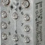
B&R X67BCJ321.L12
Fieldbus: Modbus/TCP, Modbus/UDPIntegrated 2-port switch for efficient cablingI/O configuration via the fieldbusDHCP-capableResponse time:
Request for Quote
Shipping & Delivery
-
 Courier delivery
Our courier will deliver to the specified address
5-6 Days
From €20
-
 DHL Courier delivery
DHL courier will deliver to the specified address
2-3 Days
From €40
-
 Warranty 1 year
-
 Free 30-Day returns
Description
Fieldbus: Modbus/TCP, Modbus/UDPIntegrated 2-port switch for efficient cablingI/O configuration via the fieldbusDHCP-capableResponse time:
Specification
| Bus controller | 0xAD3C |
|---|---|
| Inputs/Outputs | 8x M12, A-coded |
| Insulation voltage between channel and bus | 500 Veff |
| Nominal voltage | 24 VDC |
| Internal I/O module | 0xBD76 |
| Sensor/Actuator power supply | Max. 12 W |
| Status indicators | I/O function per channel, supply voltage, bus function |
| Outputs | Yes, using LED status indicator and software |
| I/O power supply | M8, 4-pin |
| Fieldbus | 1 ms |
| X2X Link | 500 μs |
| Power output | 15 W X2X Link power supply for I/O modules |
| Internal I/O | 2.5 W |
| X2X Link power supply | 24.3 W at maximum power output for connected I/O modules |
| CE | Yes |
| UKCA | Yes |
| CRA (Cyber Resilience Act) | Evaluation ongoing |
| ATEX | Zone 2, II 3G Ex nA IIA T5 Gc IP67, Ta = 0 – Max. 60°C TÜV 05 ATEX 7201X |
| UL | cULus E115267 Industrial control equipment |
| HazLoc | cCSAus 244665 Process control equipment for hazardous locations Class I, Division 2, Groups ABCD, T5 |
| KC | Yes |
| Variant | Current-sourcing FET |
| Line length | Max. 100 m between 2 stations (segment length) |
| Transfer rate | 10/100 Mbit/s |
| Physical layer | 10BASE-T/100BASE-TX |
| Half-duplex | Yes |
| Full-duplex | Yes |
| Autonegotiation | Yes |
| Auto-MDI/MDIX | Yes |
| Synchronization between bus systems possible | No |
| Voltage range | 18 to 30 VDC |
| Integrated protective function | Reverse polarity protection |
| Voltage | I/O power supply minus voltage drop for short-circuit protection |
| Voltage drop for short-circuit protection at 0.5 A | Max. 2 VDC |
| Summation current | Max. 0.5 A |
| Short-circuit proof | Yes |
| Input characteristics per EN 61131-2 | Type 1 |
| Input voltage | 18 to 30 VDC |
| Input current at 24 VDC | Typ. 4 mA |
| Input circuit | Sink |
| Hardware | ≤10 μs (channels 1 to 4) / ≤70 µs (channels 5 to 16) |
| Software | Default 0 ms, configurable between 0 and 25 ms in 0.2 ms intervals |
| Input resistance | Typ. 6 kΩ |
| Additional functions | 50 kHz event counting, gate measurement |
| Low | <5 VDC |
| High | >15 VDC |
| Quantity | 1 |
| Signal form | Square wave pulse |
| Evaluation | Positive edge – Negative edge |
| Input frequency | Max. 50 kHz |
| Counter 1 | Input 1 |
| Counter 2 | Input 3 |
| Counter frequency | Max. 50 kHz |
| Counter size | 16-bit |
| Internal | 48 MHz, 3 MHz, 187.5 kHz |
| Length of pause between pulses | ≥100 µs |
| Pulse length | ≥20 µs |
| Supported inputs | Input 2 or input 4 |
| Switching voltage | I/O power supply minus residual voltage |
| Nominal output current | 0.5 A |
| Total nominal current | 8 A |
| Output circuit | Source |
| Output protection | Thermal shutdown in the event of overcurrent or short circuit, integrated protection for switching inductive loads, reverse polarity protection of the output power supply |
| Diagnostic status | Output monitoring with 10 ms delay |
| Leakage current when the output is switched off | 5 µA |
| Switching on after overload shutdown | Approx. 10 ms (depends on the module temperature) |
| Residual voltage | <0.3 V at 0.5 A nominal current |
| Peak short-circuit current | <12 A |
| 0 → 1 | <400 µs |
| 1 → 0 | <400 µs |
| Resistive load | Max. 100 Hz |
| Inductive load | See section “Switching inductive loads”. |
| Braking voltage when switching off inductive loads | 50 VDC |
| Electrical isolation | Bus isolated from channel Modbus not isolated from bus and channel not isolated from channel |
| Any | Yes |
| 0 to 2000 m | No limitation |
| >2000 m | Reduction of ambient temperature by 0.5°C per 100 m |
| Degree of protection per EN 60529 | IP67 |
| Operation | -25 to 60°C |
| Derating | – |
| Storage | -40 to 85°C |
| Transport | -40 to 85°C |
| Width | 53 mm |
| Height | 155 mm |
| Depth | 42 mm |
| Weight | 350 g |
| M8 | Max. 0.4 Nm |
| M12 | Max. 0.6 Nm |
Customer Reviews
Rated 0 out of 5
0 reviews
Rated 5 out of 5
0
Rated 4 out of 5
0
Rated 3 out of 5
0
Rated 2 out of 5
0
Rated 1 out of 5
0
Be the first to review “B&R X67BCJ321.L12” Cancel reply
Reviews
Clear filtersThere are no reviews yet.