")
Fast delivery within 72 Hours
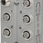
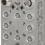
B&R X67BC4321
Fieldbus: CANopen8 digital channels, can be configured as input or outputSimple I/O configuration via the fieldbusIntegrated connection to the local expansions via X2X Link for 39 additional modulesCo…
Request for Quote
Shipping & Delivery
-
 Courier delivery
Our courier will deliver to the specified address
5-6 Days
From €20
-
 DHL Courier delivery
DHL courier will deliver to the specified address
2-3 Days
From €40
-
 Warranty 1 year
-
 Free 30-Day returns
Description
Fieldbus: CANopen8 digital channels, can be configured as input or outputSimple I/O configuration via the fieldbusIntegrated connection to the local expansions via X2X Link for 39 additional modulesConfigurable I/O cycle (0.4 to 1.3 ms)
CAN (Controller Area Network) has become considerably widespread in automation technology. CAN topology is based on a line structure and uses twisted pair wires for data transfer. CANopen is a higher-layer protocol based on CAN. This standardized protocol offers highly flexible configuration possibilities.This bus controller makes it possible to connect X2X Link I/O nodes to CANopen. The bus controller has automatic transfer rate detection and AutoMapping of the I/O modules connected with X2X Link. All CANopen operating modes such as synchronous, event and polling modes are supported together with PDO linking, life/node guarding, emergency objects and much more.Note:Only the default function model is supported (see respective module description) by the bus controller for multi-function modules.
Specification
| Bus controller |
0x17D4 |
|---|---|
| Inputs/Outputs |
8x M8, 3-pin |
| Insulation voltage between channel and bus |
500 Veff |
| Nominal voltage |
24 VDC |
| Internal I/O module |
0x1311 |
| Sensor/Actuator power supply |
Max. 12 W |
| Status indicators |
I/O function per channel, supply voltage, bus function |
| Outputs |
Yes, using LED status indicator and software |
| I/O power supply |
M8, 4-pin |
| Fieldbus |
No limitation |
| X2X Link |
400 μs |
| Power output |
3 W X2X Link power supply for I/O modules |
| Internal I/O |
2 W |
| X2X Link power supply |
6.6 W at maximum power output for connected I/O modules |
| CE |
Yes |
| UKCA |
Yes |
| ATEX |
Zone 2, II 3G Ex nA IIA T5 GcIP67, Ta = 0 – Max. 60°CTÜV 05 ATEX 7201X |
| UL |
cULus E115267Industrial control equipment |
| HazLoc |
cCSAus 244665Process control equipmentfor hazardous locations Class I, Division 2, Groups ABCD, T5 |
| KC |
Yes |
| Variant |
Current-sourcing FET |
| Max. distance |
1000 m |
| Transfer rate |
Max. 1 Mbit/s |
| Default transfer rate |
Automatic transfer rate detection |
| Synchronization between bus systems possible |
No |
| Terminating resistor |
Can be optionally screwed onto the Y-connector |
| Voltage range |
18 to 30 VDC |
| Integrated protection |
Reverse polarity protection |
| Voltage |
Module power supply minus voltage drop for short-circuit protection |
| Voltage drop for short-circuit protection at 0.5 A |
Max. 2 VDC |
| Summation current |
Max. 0.5 A |
| Short-circuit proof |
Yes |
| Input voltage |
18 to 30 VDC |
| Input current at 24 VDC |
Typ. 4 mA |
| Input circuit |
Sink |
| Hardware |
≤10 μs (channels 1 to 4) / ≤70 µs (channels 5 to 8) |
| Software |
Default 0 ms, configurable between 0 and 25 ms in 0.1 ms intervals |
| Input resistance |
Typ. 6 kΩ |
| Additional functions |
50 kHz event counting, gate measurement |
| Low |
<5 VDC |
| High |
>15 VDC |
| Quantity |
1 |
| Signal form |
Square wave pulse |
| Evaluation |
Positive edge – Negative edge |
| Input frequency |
Max. 50 kHz |
| Counter 1 |
Input 1 |
| Counter 2 |
Input 3 |
| Counter frequency |
Max. 50 kHz |
| Counter size |
16-bit |
| Internal |
48 MHz, 3 MHz, 187.5 kHz |
| Length of pause between pulses |
≥100 µs |
| Pulse length |
≥20 µs |
| Supported inputs |
Input 2 or input 4 |
| Switching voltage |
Module power supply minus residual voltage |
| Nominal output current |
0.5 A |
| Total nominal current |
4 A |
| Output circuit |
Source |
| Output protection |
Thermal shutdown in the event of overcurrent or short circuit, integrated protection for switching inductive loads, reverse polarity protection of the output power supply |
| Diagnostic status |
Output monitoring with 10 ms delay |
| Leakage current when the output is switched off |
5 µA |
| Switching on after overload shutdown |
Approx. 10 ms (depends on the module temperature) |
| Residual voltage |
<0.3 V at 0.5 A nominal current |
| Peak short-circuit current |
<12 A |
| 0 → 1 |
<400 µs |
| 1 → 0 |
<400 µs |
| Resistive load |
Max. 100 Hz |
| Inductive load |
See section "Switching inductive loads". |
| Braking voltage when switching off inductive loads |
50 VDC |
| Electrical isolation |
Channel isolated from CANopen and busCANopen not isolated from bus and channel not isolated from channel |
| Any |
Yes |
| 0 to 2000 m |
No limitation |
| >2000 m |
Reduction of ambient temperature by 0.5°C per 100 m |
| Degree of protection per EN 60529 |
IP67 |
| Operation |
0 to 60°C |
| Derating |
– |
| Storage |
-25 to 85°C |
| Transport |
-25 to 85°C |
| Width |
53 mm |
| Height |
85 mm |
| Depth |
42 mm |
| Weight |
200 g |
| M8 |
Max. 0.4 Nm |
| M12 |
Max. 0.6 Nm |
Reviews
Clear filtersThere are no reviews yet.