
")
Fast delivery within 72 Hours
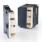
B&R 8I74S200150.00-000
ACOPOSinverter P74new, 1x 200-240 V, 1.5 kW, integrated EMC filter and brake chopper, shield plate included in delivery.
Request for Quote
Shipping & Delivery
-
 Courier delivery
Our courier will deliver to the specified address
5-6 Days
From €20
-
 DHL Courier delivery
DHL courier will deliver to the specified address
2-3 Days
From €40
-
 Warranty 1 year
-
 Free 30-Day returns
Description
ACOPOSinverter P74new, 1x 200-240 V, 1.5 kW, integrated EMC filter and brake chopper, shield plate included in delivery.
Specification
| CE | Yes |
|---|---|
| UL | UL E225616Power conversion equipment |
| CSA | CSA E272421Industrial control equipment |
| Specified on nameplate | 1.5 kW (2 HP) |
| Mains input voltage | 1x 200 VAC -15% to 240 VAC +10% |
| Frequency | 50 to 60 Hz ±5% |
| Apparent power (at 240 VAC) | 3.6 kVA |
| Max. assumed short-circuit current (Isc)(short-circuit current at connection point) | 1 kA |
| Inrush current | Max. 19.1 A |
| At 200 VAC | 17.6 A |
| At 240 VAC | 14.8 A |
| Power dissipation at nominal load and nominal clock frequency | 81 W |
| Integrated EMC filter | Yes |
| Motor cable length per IEC/EN 61800-3 Cat. C1 environment 1 (public power network) | C1 level of 2 to 16 kHz with 20 m cable |
| Motor cable length per IEC/EN 61800-3 Cat. C2 environment 1 (public power network) | C2 level of 2 to 6 kHz with 50 m cableC2 level at 2 kHz with 100 m cable |
| Motor cable length per IEC/EN 61800-3 Cat. C3 environment 2 (industrial power system) | 50 m |
| With add-on filter | 8I0FS016.200-1 |
| Nominal output current | 8 A |
| At nominal clock frequency (4 kHz) | No derating (up to 50°C) |
| Other clock frequencies | The derating curves are included in the installation instructions, which can be downloaded from www.br-automation.com. |
| Starting at 1000 m above sea level | 1%, per 100 m |
| Max. transient current for 60 s | 12 A |
| Max. transient current for 2 s | 13.2 A |
| Output frequency range | 0.1 to 599 Hz |
| Nominal clock frequency | 4 kHz |
| Min. | 2 kHz |
| Max. | 16 kHz |
| With braking resistor | Up to 170% of the nominal motor torque |
| Shielded cable | 50 m |
| Non-shielded cable | 100 m |
| Induction motor | Sensorless vector control:1. With V/f characteristic curve for constant torque→ Default profile2. With V/f characteristic curve for quadratically increasing torque→ Energy-saving profile, e.g. for fans and pumpsSensorless slip control:1. With V/f characteristic curve for constant torque→ Default profile2. With V/f characteristic curve for constant torque (6 f ranges)→ Profile for individual special applications3. With V/f characteristic curve for quadratically increasing torque→ Energy-saving profile, e.g. for fans and pumps |
| Synchronous motor | Sensorless vector control:1. With V/f characteristic curve for constant torque→ Default profile |
| Main protective functions of inverter | Thermal protection against power stage overheatingProtection against short circuits between motor phases, overcurrent between output phases and ground, overvoltages on the DC bus, exceeding the speed limit. Safety function for: Overvoltage and undervoltage of the mains supply, mains phase failure with 3-phase power supply |
| Integrated dynamic brake transistors | Yes |
| Min. resistance value (external) | 27 Ω |
| Input voltage | 24 VDC (-15%/+20%) |
| Current | 800 Ω |
| Output voltage 24 VDC | 24 VDC (-15%/+20%) |
| Max. output current at 24 VDC | 100 mA |
| Output voltage 10 VDC | 10 VDC (-0%/+10%) |
| Max. output current at 10 VDC | 10 mA |
| Type | Type 2 |
| Quantity | 1 |
| Nominal voltage | 30 VDC / 250 VAC |
| Input circuit | Sink |
| Current consumption | 16 mA |
| Input - ACOPOSinverter | Yes |
| Input - Input | No |
| Sampling time | 2 ms |
| Input impedance | 1.5 kΩ |
| Max. input frequency | 20 kHz |
| Low | <2 V |
| High | >17 V |
| Voltage | 470 Ω |
| Resolution | 10-bit |
| Max. voltage | 30 VDC |
| Output circuit | Source or sink |
| Max. current | 100 mA |
| Switching capacity | R1, with resistive load (cos phi = 1): 3 A at 250 VAC, R1, with resistive load (cos phi = 1): 4 A at 30 VDC, R1, R2, with inductive load (cos = 0.4 and L/R = 7 ms): 2 A at 250 VAC, R1, R2, with inductive load (cos = 0.4 and L/R = 7 ms): 2 A at 30 VDC, R2 with resistive load (cos phi = 1): 5 A at 250 VAC, R2 with resistive load (cos phi = 1): 5 A at 30 VDC |
| Relay 1 | 1 changeover contact |
| Relay 2 | 1 normally open contact |
| Output - ACOPOSinverter | Yes |
| Output - Output | No |
| Response time (max.) | 2 ms |
| Output | 0 to 10 V or 0 to 20 mA |
| Update time | 2 ms |
| Degree of protection per EN 60529 | IP20 |
| Relative humidity per IEC 60068-2-3 | 5 to 95%. non-condensingNo dripping water |
| Maximum installation elevation | Up to 2000 m |
| Max. pollution degree per IEC/EN 61800-5-1 | 2 (non-conductive pollution) |
| Ambient conditions per IEC 60721-3-3 | Class 3C3 and 3S3 |
| Operating position | Vertical mounting orientation ±10% |
| Operation | -10 to 50°C without derating50 to 60°C with derating |
| Storage | -25 to 70°C |
| Max. vibration resistance | 1 gn 13 to 200 Hz EN/IEC 60068-2-61.5 mm peak to peak 3 to 13 Hz EN/IEC 60068-2-6 |
| Width | 60 mm |
| Height | 317 mm |
| Depth | 245 mm |
| Weight | 1.952 kg |
Customer Reviews
Rated 0 out of 5
0 reviews
Rated 5 out of 5
0
Rated 4 out of 5
0
Rated 3 out of 5
0
Rated 2 out of 5
0
Rated 1 out of 5
0
Be the first to review “B&R 8I74S200150.00-000” Cancel reply
Reviews
Clear filtersThere are no reviews yet.