
")
Fast delivery within 72 Hours
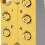
B&R X67SC4122.L12
8 safe digital inputs, sink circuit8 pulse outputsSoftware input filter configurable for each channel4 safe digital outputs, output type B with 2 A, source circuitNode number switches for setting the…
Request for Quote
Shipping & Delivery
-
 Courier delivery
Our courier will deliver to the specified address
5-6 Days
From €20
-
 DHL Courier delivery
DHL courier will deliver to the specified address
2-3 Days
From €40
-
 Warranty 1 year
-
 Free 30-Day returns
Description
8 safe digital inputs, sink circuit8 pulse outputsSoftware input filter configurable for each channel4 safe digital outputs, output type B with 2 A, source circuitNode number switches for setting the X2X Link addressIntegrated output protection
The module is equipped with 8 safe digital inputs and 4 safe digital outputs. They are designed for a nominal voltage of 24 VDC.The module can be used to read in digital signals and to control actuators in safety-related applications up to PL e or SIL 3.The node number switch for setting the X2X Link address is a unique feature. When modular machine configurations change, it is necessary, for example, to define specific module groups at a fixed address that is independent of the preceding modules in the line. All subsequent standard modules refer to this offset and use it automatically for addressing purposes.The module is equipped with filters that are individually configurable for switch-on and switch-off behavior. The module also provides pulse signals for diagnosing the sensor line.The outputs are designed using semiconductor technology so that the safety-related characteristics do not depend on the number of operating cycles. The “high-side high-side” variant (output type B) is required for actuators with reference potential (e.g. Enable inputs on frequency inverters). It is important to observe the special notices for the cabling in this case. Safe digital output channels provide protection against automatic restart when network errors occur.
Specification
| I/O module | 8 safe type A digital inputs, 8 pulse outputs, 24 VDC, 4 safe type B1 digital outputs, 24 VDC, 2 A, OSSD <500 µs |
|---|---|
| B&R ID code | 0xA7A6 |
| Status indicators | I/O function per channel, operating state, module status |
| Module run/error | Yes, using LED status indicator and software |
| Outputs | Yes, using LED status indicator and software |
| Inputs | Yes, using LED status indicator and software |
| Scope | Module |
| Function | Module functionality |
| Standalone mode | No |
| Max. I/O cycle time | 1 ms |
| X2X Link | M12, B-coded |
| Inputs/Outputs | M12, A-coded |
| I/O power supply | M8, 4-pin |
| Bus | 0.8 W |
| Internal I/O | 1.8 W |
| Safe digital outputs | 2.25 |
| Pulse outputs | 0.08 |
| Channel - Bus | Yes |
| Channel - Channel | No |
| CE | Yes |
| UKCA | Yes |
| CRA (Cyber Resilience Act) | In preparation |
| Functional safety | EN 50156-1:2004 |
| ATEX | Zone 2, II 3G Ex nA IIA T5 GcIP67, Ta = 0 – Max. 60°CTÜV 05 ATEX 7201X |
| UL | cULus E115267Industrial control equipment |
| HazLoc | cCSAus 244665Process control equipmentfor hazardous locations Class I, Division 2, Groups ABCD, T5 |
| KC | Yes |
| Note | See section “Safety characteristics”. |
| Nominal voltage | 24 VDC |
| Voltage range | 18 to 30 VDC |
| Integrated protective function | Reverse polarity protection |
| Quantity | 8 |
| Variant | Push-Pull |
| Input characteristics per EN 61131-2 | Type 1 |
| Hardware | ≤150 μs |
| Software | Configurable between 0 and 500 ms |
| Input circuit | Sink |
| Input voltage | 24 VDC -15% / +20% |
| Input current at 24 VDC | Min. 2 mA to max. 4.59 mA |
| Input resistance | Min. 5.23 kΩ |
| Error detection time | 1 s |
| Insulation voltage between channel and bus | 500 Veff |
| Low | <5 VDC |
| High | >15 VDC |
| Line length between signal source (pulse output or external signal) and input | Max. 60 m with unshielded lineMax. 400 m with shielded line |
| Nominal output current | 50 mA |
| Total nominal current | 400 mA |
| Output protection | Shutdown of individual channels in the event of overload or short circuit |
| Braking voltage when switching off inductive loads | Max. 45 VDC |
| Peak short-circuit current | 25 A for 5 ms |
| Leakage current when the output is switched off | 0.1 mA |
| RDS(on) | 4 Ω |
| Switching voltage | I/O power supply minus voltage drop due to RDS(on) |
| Max. switching frequency | See section “Inrush current behavior for output channels”. |
| Test pulse length | Max. 1 ms |
| Max. capacitive load | 100 nF |
| Peak output current | 2.5 A (effective current ≤2 A) |
| Minimum load | 12 mA, hardware revision I0 and later: 0 mA |
| IOUT | <3 mA, hardware revision B2 and later: <1 mA, hardware revision I0 and later: <100 μA |
| IGND | <110 mA |
| Short-circuit current | 1.4 Aeff |
| Any | Yes |
| Installation elevation above sea level | 0 to 2000 m, no limitation |
| Degree of protection per EN 60529 | IP67 |
| Operation | -40 to 60°C |
| Storage | -40 to 85°C |
| Transport | -40 to 85°C |
| Width | 53 mm |
| Height | 155 mm |
| Depth | 42 mm |
| Weight | 350 g |
| M8 | Max. 0.4 Nm |
| M12 | Max. 0.6 Nm |
Reviews
Clear filtersThere are no reviews yet.