")
Fast delivery within 72 Hours
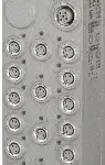
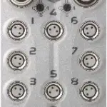
B&R X67BC6321.L12
Fieldbus: PROFIBUS DPIntegrated Y-connector for fieldbus connection16 digital channels, configurable as inputs or outputsM12 connectionsSimple I/O configuration via the fieldbusIntegrated connection t…
Request for Quote
Shipping & Delivery
-
 Courier delivery
Our courier will deliver to the specified address
5-6 Days
From €20
-
 DHL Courier delivery
DHL courier will deliver to the specified address
2-3 Days
From €40
-
 Warranty 1 year
-
 Free 30-Day returns
Description
Fieldbus: PROFIBUS DPIntegrated Y-connector for fieldbus connection16 digital channels, configurable as inputs or outputsM12 connectionsSimple I/O configuration via the fieldbusIntegrated connection to local expansions via X2X Link for 63 additional modulesConfigurable I/O cycle (0.2 to 1 ms)
PROFIBUS DP is based on the physics of the RS485 interface. Data transfer is controlled using a hybrid bus access procedure: Active stations receive communication rights via a token passing procedure and can then access all stations on the network according to the master-slave principle. The maximum time of circulation for a token can be configured, which results in a defined cycle time.Access represents various services for the user for both cyclic and for acyclic data transfer.This bus controller makes it possible to connect X2X Link I/O nodes to PROFIBUS DP. It supports PROFIBUS DP with all of its options and other additional properties. In addition to the device, module and channel diagnostics provided in the PROFIBUS standard, it is also possible, for example, to switch to the slot diagnostics option in S7 format. X67 or other modules based on X2X Link can be connected to the bus controller. The configuration of the modular system is optimally supported by PROFIBUS DP.With multifunction modules, the bus controller supports only the default function model in the event of automatic configuration by the bus controller (see the respective module description).
Specification
| Bus controller | 0x1AEC |
|---|---|
| Inputs/Outputs | 8x M12, A-coded |
| Insulation voltage between channel and bus | 500 Veff |
| Nominal voltage | 24 VDC |
| Internal I/O module | 0x1A1D |
| Sensor/Actuator power supply | Max. 12 W |
| Status indicators | I/O function per channel, supply voltage, bus function |
| Outputs | Yes, using LED status indicator and software |
| I/O power supply | M8, 4-pin |
| Fieldbus | No limitation |
| X2X Link | 400 μs |
| Power output | 15 W X2X Link power supply for I/O modules |
| Internal I/O | 2.04 W |
| X2X Link power supply | 23.63 W at maximum power output for connected I/O modules |
| CE | Yes |
| UKCA | Yes |
| CRA (Cyber Resilience Act) | In preparation |
| ATEX | Zone 2, II 3G Ex nA IIA T5 Gc IP67, Ta = 0 – Max. 60°C TÜV 05 ATEX 7201X |
| UL | cULus E115267 Industrial control equipment |
| HazLoc | cCSAus 244665 Process control equipment for hazardous locations Class I, Division 2, Groups ABCD, T5 |
| KC | Yes |
| Variant | Current-sourcing FET |
| Max. distance | 1200 m |
| Transfer rate | Max. 12 Mbit/s |
| Default transfer rate | Automatic transfer rate detection |
| Synchronization between bus systems possible | No |
| PROFIBUS DP ID | 0xBC61 |
| Terminating resistor | Can be optionally screwed onto the integrated Y-connector |
| Voltage range | 18 to 30 VDC |
| Integrated protective function | Reverse polarity protection |
| Voltage | I/O power supply minus voltage drop for short-circuit protection |
| Voltage drop for short-circuit protection at 0.5 A | Max. 2 VDC |
| Summation current | Max. 0.5 A |
| Short-circuit proof | Yes |
| Input characteristics per EN 61131-2 | Type 1 |
| Input voltage | 18 to 30 VDC |
| Input current at 24 VDC | Typ. 4 mA |
| Input circuit | Sink |
| Hardware | ≤10 μs (channels 1 to 4) / ≤70 µs (channels 5 to 16) |
| Software | Default 0 ms, configurable between 0 and 25 ms in 0.2 ms intervals |
| Input resistance | Typ. 6 kΩ |
| Additional functions | 50 kHz event counting, gate measurement |
| Low | <5 VDC |
| High | >15 VDC |
| Quantity | 1 |
| Signal form | Square wave pulse |
| Evaluation | Positive edge – Negative edge |
| Input frequency | Max. 50 kHz |
| Counter 1 | Input 1 |
| Counter 2 | Input 3 |
| Counter frequency | Max. 50 kHz |
| Counter size | 16-bit |
| Internal | 48 MHz, 3 MHz, 187.5 kHz |
| Length of pause between pulses | ≥100 µs |
| Pulse length | ≥20 µs |
| Supported inputs | Input 2 or input 4 |
| Switching voltage | I/O power supply minus residual voltage |
| Nominal output current | 0.5 A |
| Total nominal current | 8 A |
| Output circuit | Source |
| Output protection | Thermal shutdown in the event of overcurrent or short circuit, integrated protection for switching inductive loads, reverse polarity protection of the output power supply |
| Diagnostic status | Output monitoring with 10 ms delay |
| Leakage current when the output is switched off | 5 µA |
| Switching on after overload shutdown | Approx. 10 ms (depends on the module temperature) |
| Residual voltage | <0.3 V at 0.5 A nominal current |
| Peak short-circuit current | <12 A |
| 0 → 1 | <400 µs |
| 1 → 0 | <400 µs |
| Resistive load | Max. 100 Hz |
| Inductive load | See section “Switching inductive loads”. |
| Braking voltage when switching off inductive loads | 50 VDC |
| Electrical isolation | Channel isolated from PROFIBUS and bus PROFIBUS not isolated from bus and channel not isolated from channel |
| Any | Yes |
| 0 to 2000 m | No limitation |
| >2000 m | Reduction of ambient temperature by 0.5°C per 100 m |
| Degree of protection per EN 60529 | IP67 |
| Operation | -25 to 60°C |
| Derating | – |
| Storage | -40 to 85°C |
| Transport | -40 to 85°C |
| Width | 53 mm |
| Height | 155 mm |
| Depth | 42 mm |
| Weight | 375 g |
| M8 | Max. 0.4 Nm |
| M12 | Max. 0.6 Nm |
Reviews
Clear filtersThere are no reviews yet.