")
Fast delivery within 72 Hours
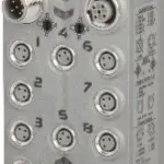
B&R X67BC4321-10
Fieldbus: CANopen8 digital channels, configurable as inputs or outputsAuto-configuration of I/O modulesConvenient I/O configuration with Automation Studio V4.3 and laterConstant response times even wi…
Request for Quote
Shipping & Delivery
-
 Courier delivery
Our courier will deliver to the specified address
5-6 Days
From €20
-
 DHL Courier delivery
DHL courier will deliver to the specified address
2-3 Days
From €40
-
 Warranty 1 year
-
 Free 30-Day returns
Description
Fieldbus: CANopen8 digital channels, configurable as inputs or outputsAuto-configuration of I/O modulesConvenient I/O configuration with Automation Studio V4.3 and laterConstant response times even with large amounts of data (max. 32 Rx and 32 Tx PDOs)Configurable I/O cycle (0.5 to 4 ms)Possible to configure the transfer rate or have it detected automaticallyHeartbeat consumer and producer, emergency producer2x SDO server, NMT slaveSimple bootup (autostart)
Controller Area Network (CAN) is widespread in automation technology. CAN topology is based on a line structure and uses twisted wire pairs for data transfer. CANopen is a higher-layer protocol based on CAN. The standardized protocol offers very flexible configuration options.This bus controller makes it possible to connect up to 253 X2X Link I/O modules to CANopen. A transition between IP20 and IP67 protection is possible by directly connecting X20, X67 or XV modules to one another at distances of up to 100 m each across control cabinet boundaries as required. All CANopen operating modes such as synchronous, event and polling are supported as well as PDO linking, life/node guarding, heartbeat, emergency objects and much more. With multifunction modules, the bus controller supports only the default function model in the event of automatic configuration by the bus controller (see the respective module description). Automation Studio V4.3 or later can be used to easily create configuration files (e.g. DCF files). All other function models are also supported by transferring configuration data to the bus controller (e.g. via the master environment with an SDO download). Automation Studio can be downloaded at no cost from the B&R website (www.br-automation.com). The evaluation license is permitted to be used to create complete configurations for fieldbus bus controllers at no cost.
Specification
| Bus controller | 0xA90D |
|---|---|
| Inputs/Outputs | 8x M8, 3-pin |
| Insulation voltage between channel and bus | 500 Veff |
| Nominal voltage | 24 VDC |
| Internal I/O module | 0xB528 |
| Sensor/Actuator power supply | Max. 12 W |
| Status indicators | I/O function per channel, supply voltage, bus function |
| Outputs | Yes, using LED status indicator and software |
| I/O power supply | M8, 4-pin |
| Fieldbus | No limitation |
| X2X Link | 500 μs |
| Power output | 3 W X2X Link power supply for I/O modules |
| Internal I/O | 2.1 W |
| X2X Link power supply | 6 W at maximum power output for connected I/O modules |
| CE | Yes |
| UKCA | Yes |
| CRA (Cyber Resilience Act) | In preparation |
| ATEX | Zone 2, II 3G Ex nA IIA T5 Gc IP67, Ta = 0 – Max. 60°C TÜV 05 ATEX 7201X |
| UL | cULus E115267 Industrial control equipment |
| HazLoc | cCSAus 244665 Process control equipment for hazardous locations Class I, Division 2, Groups ABCD, T5 |
| KC | Yes |
| Variant | Current-sourcing FET |
| Max. distance | 1000 m |
| Transfer rate | Max. 1 Mbit/s |
| Default transfer rate | Automatic transfer rate detection |
| Synchronization between bus systems possible | No |
| Terminating resistor | Can be optionally screwed onto the Y-connector |
| Voltage range | 18 to 30 VDC |
| Integrated protective function | Reverse polarity protection |
| Voltage | I/O power supply minus voltage drop for short-circuit protection |
| Voltage drop for short-circuit protection at 0.5 A | Max. 2 VDC |
| Summation current | Max. 0.5 A |
| Short-circuit proof | Yes |
| Input characteristics per EN 61131-2 | Type 1 |
| Input voltage | 18 to 30 VDC |
| Input current at 24 VDC | Typ. 4 mA |
| Input circuit | Sink |
| Hardware | ≤10 μs (channels 1 to 4) / ≤70 µs (channels 5 to 8) |
| Software | Default 0 ms, configurable between 0 and 25 ms in 0.1 ms intervals |
| Input resistance | Typ. 6 kΩ |
| Additional functions | 50 kHz event counting, gate measurement |
| Low | <5 VDC |
| High | >15 VDC |
| Quantity | 1 |
| Signal form | Square wave pulse |
| Evaluation | Positive edge – Negative edge |
| Input frequency | Max. 50 kHz |
| Counter 1 | Input 1 |
| Counter 2 | Input 3 |
| Counter frequency | Max. 50 kHz |
| Counter size | 16-bit |
| Internal | 48 MHz, 3 MHz, 187.5 kHz |
| Length of pause between pulses | ≥100 µs |
| Pulse length | ≥20 µs |
| Supported inputs | Input 2 or input 4 |
| Switching voltage | I/O power supply minus residual voltage |
| Nominal output current | 0.5 A |
| Total nominal current | 4 A |
| Output circuit | Source |
| Output protection | Thermal shutdown in the event of overcurrent or short circuit, integrated protection for switching inductive loads, reverse polarity protection of the output power supply |
| Diagnostic status | Output monitoring with 10 ms delay |
| Leakage current when the output is switched off | 5 µA |
| Switching on after overload shutdown | Approx. 10 ms (depends on the module temperature) |
| Residual voltage | <0.3 V at 0.5 A nominal current |
| Peak short-circuit current | <12 A |
| 0 → 1 | <400 µs |
| 1 → 0 | <400 µs |
| Resistive load | Max. 100 Hz |
| Inductive load | See section “Switching inductive loads”. |
| Braking voltage when switching off inductive loads | 50 VDC |
| Electrical isolation | Bus isolated from CANopen and channel Channel isolated from CANopen Channel not isolated from channel |
| Any | Yes |
| 0 to 2000 m | No limitation |
| >2000 m | Reduction of ambient temperature by 0.5°C per 100 m |
| Degree of protection per EN 60529 | IP67 |
| Operation | -25 to 60°C |
| Derating | – |
| Storage | -40 to 85°C |
| Transport | -40 to 85°C |
| Width | 53 mm |
| Height | 85 mm |
| Depth | 42 mm |
| Weight | 200 g |
| M8 | Max. 0.4 Nm |
| M12 | Max. 0.6 Nm |
Reviews
Clear filtersThere are no reviews yet.