
")
Fast delivery within 72 Hours
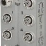
B&R X67AI2744
2 full-bridge strain gauge inputsData output rate configurable from 2.5 Hz to 7.5 kHz
The module is equipped with 2 inputs for evaluating full-bridge strai…
Request for Quote
Shipping & Delivery
-
 Courier delivery
Our courier will deliver to the specified address
5-6 Days
From €20
-
 DHL Courier delivery
DHL courier will deliver to the specified address
2-3 Days
From €40
-
 Warranty 1 year
-
 Free 30-Day returns
Description
2 full-bridge strain gauge inputsData output rate configurable from 2.5 Hz to 7.5 kHz
The module is equipped with 2 inputs for evaluating full-bridge strain gauges and works with both 4-wire and 6-wire strain gauge load cells. The concept applied by the module requires calibration in the measurement system. This calibration compensates or eliminates the absolute inaccuracies in the measurement circuit (e.g. component tolerances, effective bridge voltage or zero offset). The measuring accuracy related to an absolute (calibrated) value only changes due to the negative influence of a change in the operating temperature.
Specification
| I/O module | 2 full-bridge strain gauge inputs |
|---|---|
| B&R ID code | 0x8820 |
| Status indicators | Channel status, operating state, module status |
| Module run/error | Yes, using LED status indicator and software |
| Open circuit | Yes, using LED status indicator and software |
| Input | Yes, using LED status indicator and software |
| X2X Link | M12, B-coded |
| Inputs | 4x M12, A-coded |
| I/O power supply | M8, 4-pin |
| Bus | 0.75 W |
| Internal I/O | 2.4 W |
| CE | Yes |
| UKCA | Yes |
| CRA (Cyber Resilience Act) | In preparation |
| ATEX | Zone 2, II 3G Ex nA IIA T5 Gc IP67, Ta = 0 – Max. 60°C TÜV 05 ATEX 7201X |
| UL | cULus E115267 Industrial control equipment |
| HazLoc | cCSAus 244665 Process control equipment for hazardous locations Class I, Division 2, Groups ABCD, T5 |
| KC | Yes |
| Nominal voltage | 24 VDC |
| Voltage range | 18 to 30 VDC |
| Integrated protective function | Reverse polarity protection |
| Strain gauge factor | 2 to 256 mV/V, configurable using software |
| Connection | 4- or 6-wire connections |
| Input type | Differential, used to evaluate a full-bridge strain gauge |
| Digital converter resolution | 24-bit |
| Conversion time | Depends on the configured data output rate |
| Data output rate | 2.5 to 7,500 samples per second, configurable using software (fDATA) |
| Cutoff frequency | 5 kHz |
| Order | 3 |
| Slope | 60 dB |
| ADC filter characteristics | Sigma-delta, see section “Filter characteristics of the sigma-delta A/D converter” |
| Operating range / Measurement sensor | 85 to 5,000 Ω |
| Influence of cable length | See section “Calculation example”, sensor cable length: Max. 30 m |
| Input protection | RC protection |
| Common-mode range | 0 to 3 VDC Permissible input voltage range (with regard to the electric potential strain gauge GND) on inputs “Input +” and “Input -“ |
| Insulation voltage between input and bus | 500 Veff |
| Conversion procedure | Sigma-delta |
| Broken bridge supply line | Value approaching 0 |
| Broken sensor line | Value approaching ±end value (status bit “Line monitoring” is set in register “Module status”) |
| Valid range of values | 0xFF800001 to 0x007FFFFF (-8,388,607 to 8,388,607) |
| Voltage | 5.5 VDC / Max. 65 mA |
| Short-circuit and overload-proof | Yes |
| Voltage drop for short-circuit protection | Max. 0.2 VDC at 65 mA and 25°C |
| 2 mV/V | 1.31 nV |
| 4 mV/V | 2.62 nV |
| 8 mV/V | 5.25 nV |
| 16 mV/V | 10.49 nV |
| 32 mV/V | 20.98 nV |
| 64 mV/V | 41.96 nV |
| 128 mV/V | 83.92 nV |
| 256 mV/V | 167.85 nV |
| Max. gain drift | 12 ppm/°C |
| Max. offset drift | 2 ppm/°C |
| Nonlinearity | <10 ppm |
| Electrical isolation | Bus isolated from analog input and strain gauge supply voltage Channel not isolated from I/O power supply |
| Horizontal | Yes |
| Vertical | Yes |
| 0 to 2000 m | No limitation |
| >2000 m | Reduction of ambient temperature by 0.5°C per 100 m |
| Degree of protection per EN 60529 | IP67 |
| Operation | -25 to 60°C |
| Derating | – |
| Storage | -40 to 85°C |
| Transport | -40 to 85°C |
| Width | 53 mm |
| Height | 85 mm |
| Depth | 42 mm |
| Weight | 190 g |
| M8 | Max. 0.4 Nm |
| M12 | Max. 0.6 Nm |
Reviews
Clear filtersThere are no reviews yet.