


Fast delivery within 72 Hours
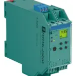
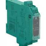
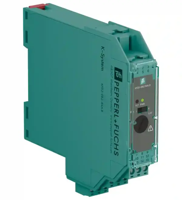
Pepperl Fuchs KFD2-EB2.R4A.B
Redundant Power Feed Module. Interface for Power Rail, Used for redundant configuration, Supply current ≤ 4 A, Replaceable fuse, Relay contact output, reversible, LED status indication. Connection: te…
Request for Quote
Shipping & Delivery
-
 Courier delivery
Our courier will deliver to the specified address
5-6 Days
From €20
-
 DHL Courier delivery
DHL courier will deliver to the specified address
2-3 Days
From €40
-
 Warranty 1 year
-
 Free 30-Day returns
Description
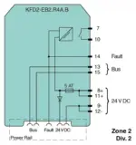
Redundant Power Feed Module. Interface for Power Rail, Used for redundant configuration, Supply current ≤ 4 A, Replaceable fuse, Relay contact output, reversible, LED status indication. Connection: terminals 11+, 12- terminals 8+, 9-. Rated voltage: 20 … 30 V DC The maximum rated operating voltage of the devices plugged onto the Power Rail must not be exceeded.. Fusing: 5 AT/250 V AC recommended maximum utilization of the fuse: 80 %. Power dissipation: ≤ 2.4 W. Connection: Power Rail. Output current: max. 4 A. Output voltage: Ui ≥ rated voltage Ur = Ui – 0.6 V. Fault signal: relay output: NO contact. Contact loading: 30 V AC/ 2 A / cos φ ≥ 0.7 ; 40 V DC/ 2 A. Energized/De-energized delay: approx. 20 ms / approx. 20 ms. Display elements: LEDs. Control elements: DIP switch. Configuration: via DIP switches. Labeling: space for labeling at the front. Electromagnetic compatibility: . Directive 2014/30/EUEN 61326-1:2013 (industrial locations): . Directive 2014/30/EU: EN 61326-1:2013 (industrial locations). Electromagnetic compatibility: NE 21:2017. Degree of protection: IEC 60529:2001. Ambient temperature: -40 … 60 °C (-40 … 140 °F) extended ambient temperature range up to 70 °C (158 °F), refer to manual for necessary mounting conditions. Degree of protection: IP20. Connection: screw terminals. Mass: approx. 100 g. Dimensions: 20 x 119 x 115 mm (0.8 x 4.7 x 4.5 inch) (W x H x D) , housing type B2. Mounting: on 35 mm DIN mounting rail acc. to EN 60715:2001. Certificate: UL 22 ATEX 2853 X. Marking II 3G Ex ec nC IIC T4 Gc: . Marking: II 3G Ex ec nC IIC T4 Gc. Directive conformity: . Directive 2014/34/EUEN IEC 60079-0:2018+AC:2020 , EN IEC 60079-7:2015+A1:2018 , EN IEC 60079-15:2019: . Directive 2014/34/EU: EN IEC 60079-0:2018+AC:2020 , EN IEC 60079-7:2015+A1:2018 , EN IEC 60079-15:2019. FM approval: FM 22 US 0031 X. Control drawing116-0160: . Control drawing: 116-0160. UL approval: E106378. CSA approval: CoC 1051840. IECEx approval: . IECEx certificateIECEx UL 16.0051XIECEx markingEx ec nC IIC T4 Gc: . IECEx certificate: IECEx UL 16.0051X. IECEx marking: Ex ec nC IIC T4 Gc. Supplementary information: Observe the certificates, declarations of conformity, instruction manuals, and manuals where applicable. For information see www.pepperl-fuchs.com.
Specification
Supply
| Connection | terminals 11+, 12- terminals 8+, 9- |
|---|---|
| Rated voltage | 20 ... 30 V DC The maximum rated operating voltage of the devices plugged onto the Power Rail must not be exceeded. |
| Fusing | 5 AT/250 V AC recommended maximum utilization of the fuse: 80 % |
| Power dissipation | ≤ 2.4 W |
Output
| Connection | Power Rail |
|---|---|
| Output current | max. 4 A |
| Output voltage | Ui ≥ rated voltage Ur = Ui - 0.6 V |
| Fault signal | relay output: NO contact |
| Contact loading | 30 V AC/ 2 A / cos φ ≥ 0.7 ; 40 V DC/ 2 A |
| Energized/De-energized delay | approx. 20 ms / approx. 20 ms |
Indicators/settings
| Display elements | LEDs |
|---|---|
| Control elements | DIP switch |
| Configuration | via DIP switches |
| Labeling | space for labeling at the front |
Directive conformity
| Electromagnetic compatibility | |
|---|---|
| Directive 2014/30/EUEN 61326-1:2013 (industrial locations) | |
| Directive 2014/30/EU | EN 61326-1:2013 (industrial locations) |
Conformity
| Electromagnetic compatibility | NE 21:2017 |
|---|---|
| Degree of protection | IEC 60529:2001 |
Ambient conditions
| Ambient temperature | -40 ... 60 °C (-40 ... 140 °F) extended ambient temperature range up to 70 °C (158 °F), refer to manual for necessary mounting conditions |
|---|
Mechanical specifications
| Degree of protection | IP20 |
|---|---|
| Connection | screw terminals |
| Mass | approx. 100 g |
| Dimensions | 20 x 119 x 115 mm (0.8 x 4.7 x 4.5 inch) (W x H x D) , housing type B2 |
| Mounting | on 35 mm DIN mounting rail acc. to EN 60715:2001 |
Data for application in connection with hazardous areas
| Certificate | UL 22 ATEX 2853 X |
|---|---|
| Marking II 3G Ex ec nC IIC T4 Gc | |
| Marking | II 3G Ex ec nC IIC T4 Gc |
| Directive conformity | |
| Directive 2014/34/EUEN IEC 60079-0:2018+AC:2020 , EN IEC 60079-7:2015+A1:2018 , EN IEC 60079-15:2019 | |
| Directive 2014/34/EU | EN IEC 60079-0:2018+AC:2020 , EN IEC 60079-7:2015+A1:2018 , EN IEC 60079-15:2019 |
International approvals
| FM approval | FM 22 US 0031 X |
|---|---|
| Control drawing116-0160 | |
| Control drawing | 116-0160 |
| UL approval | E106378 |
| CSA approval | CoC 1051840 |
| IECEx approval | |
| IECEx certificateIECEx UL 16.0051XIECEx markingEx ec nC IIC T4 Gc | |
| IECEx certificate | IECEx UL 16.0051X |
| IECEx marking | Ex ec nC IIC T4 Gc |
General information
| Supplementary information | Observe the certificates, declarations of conformity, instruction manuals, and manuals where applicable. For information see www.pepperl-fuchs.com. |
|---|
Reviews
Clear filtersThere are no reviews yet.