


Shipping & Delivery
-
 Courier delivery
Our courier will deliver to the specified address
5-6 Days
From €20
-
 DHL Courier delivery
DHL courier will deliver to the specified address
2-3 Days
From €40
-
 Warranty 1 year
-
 Free 30-Day returns
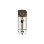
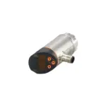
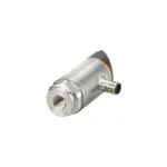
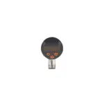
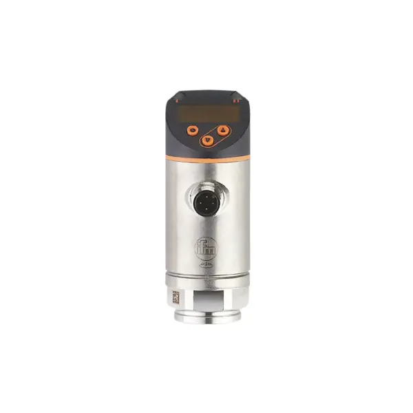
Description
Two switching outputs, one of them programmable as IO-Link and one as analogue output
Red/green display for clear identification of the acceptable range
The process connection can be rotated for optimum alignment
With long-term stability thanks to high overload protection
Robust design for use in harsh industrial environments
Convenient operation via buttons or parameter setting via IO-Link
Specification
Product characteristics
| Number of inputs and outputs | Number of digital outputs: 2; Number of analogue outputs: 1 |
|---|---|
| Measuring range | -0.125...2.5 bar -125...2500 mbar -1.8...36.25 psi -12.5...250 kPa |
| -0.125...2.5 bar | -125...2500 mbar |
| Process connection | threaded connection G 1/4 internal thread |
Application
| Special feature | Gold-plated contacts |
|---|---|
| Measuring element | ceramic-capacitive pressure measuring cell |
| Application | for industrial applications |
| Media | liquids and gases |
| Medium temperature[°C] [°C] | -25...80 |
| Min. burst pressure | 50 bar 725 psi 5000 kPa |
| 50 bar | 725 psi |
| Pressure rating | 20 bar 290 psi 2000 kPa |
| 20 bar | 290 psi |
| Vacuum resistance | -1000 mbar -0.1 MPa |
| -1000 mbar | -0.1 MPa |
| Type of pressure | relative pressure |
Electrical data
| Operating voltage[V] [V] | 18...30 DC; (to SELV/PELV) |
|---|---|
| Current consumption[mA] [mA] | < 35 |
| Min. insulation resistance[MΩ] [MΩ] | 100; (500 V DC) |
| Protection class | III |
| Reverse polarity protection | yes |
| Power-on delay time[s] [s] | 0.3 |
| Integrated watchdog | yes |
Inputs / outputs
| Number of inputs and outputs | Number of digital outputs: 2; Number of analogue outputs: 1 |
|---|
Outputs
| Total number of outputs | 2 |
|---|---|
| Output signal | switching signal; analogue signal; IO-Link; (configurable) |
| Electrical design | PNP/NPN |
| Number of digital outputs | 2 |
| Output function | normally open / normally closed; (parameterisable) |
| Max. voltage drop switching output DC[V] [V] | 2 |
| Permanent current rating of switching output DC[mA] [mA] | 250 |
| Switching frequency DC[Hz] [Hz] | < 500 |
| Number of analogue outputs | 1 |
| Analogue current output[mA] [mA] | 4...20; (scalable 1:5) |
| Max. load[Ω] [Ω] | 500 |
| Analogue voltage output[V] [V] | 0...10; (scalable 1:5) |
| Min. load resistance[Ω] [Ω] | 2000 |
| Short-circuit protection | yes |
| Type of short-circuit protection | pulsed |
| Overload protection | yes |
Measuring/setting range
| Measuring range | -0.125...2.5 bar -125...2500 mbar -1.8...36.25 psi -12.5...250 kPa |
|---|---|
| -0.125...2.5 bar | -125...2500 mbar |
| Analogue start point | -0.125...2 bar -1.8...29 psi -12.5...200 kPa |
| -0.125...2 bar | -1.8...29 psi |
| Analogue end point | 0.375...2.5 bar 5.45...36.25 psi 37.5...250 kPa |
| 0.375...2.5 bar | 5.45...36.25 psi |
| Set point SP | -0.109...2.5 bar -1.58...36.25 psi -10.9...250 kPa |
| -0.11...2.5 bar | -1.6...36.25 psi |
| Reset point rP | -0.12...2.49 bar -1.73...36.11 psi -12...249 kPa |
| -0.12...2.49 bar | -1.73...36.11 psi |
| Min. difference between SP and rP | 0.011 bar 0.15 psi 1.1 kPa |
| 0.015 bar | 0.15 psi |
| In steps of | 0.001 bar 0.01 psi 0.1 kPa |
| 0.005 bar | 0.05 psi |
| -0.109...2.5 bar | -1.58...36.25 psi |
| 0.011 bar | 0.15 psi |
| 0.001 bar | 0.01 psi |
Accuracy / deviations
| Switch point accuracy[% of the span] [% of the span] | < ± 0,4; (Turn down 1:1) |
|---|---|
| Repeatability[% of the span] [% of the span] | < ± 0,1; (with temperature fluctuations < 10 K; Turn down 1:1) |
| Characteristics deviation[% of the span] [% of the span] | < ± 0,25 (BFSL) / < ± 0,5 (LS); (Turn down 1:1; BFSL = Best Fit Straight Line; LS = limit value setting) |
| Hysteresis deviation[% of the span] [% of the span] | < ± 0,1; (Turn down 1:1) |
| Long-term stability[% of the span] [% of the span] | < ± 0,05; (Turn down 1:1; per 6 months) |
| Temperature coefficient zero point[% of the span / 10 K] [% of the span / 10 K] | 0,2; (-25...80 °C) |
| Temperature coefficient span[% of the span / 10 K] [% of the span / 10 K] | 0,2; (-25...80 °C) |
| Notes on the accuracy / deviation | switch point accuracy, linearity error under DNV GL: < ± 1%: < ± 1% |
Response times
| Response time[ms] [ms] | < 1.5 |
|---|---|
| Delay time programmable dS, dr[s] [s] | 0...50 |
| Damping process value dAP[s] [s] | 0...4 |
| Damping for the analogue output dAA[s] [s] | 0...4 |
| Max. response time analogue output[ms] [ms] | 3 |
Software / programming
| Parameter setting options | hysteresis / window; normally open / normally closed; switch-on/switch-off delay; Damping; Display unit; current/voltage output |
|---|
Interfaces
| Communication interface | IO-Link |
|---|---|
| Transmission type | COM2 (38,4 kBaud) |
| IO-Link revision | 1.1 |
| SDCI standard | IEC 61131-9 |
| SIO mode | yes |
| Required master port type | A; (when pin 2 not connected: B) |
| Supported DeviceIDs | Factory setting / CMPT = 2 464 Status_B High Resolution / CMPT = 3 975 |
| Factory setting / CMPT = 2 | 464 |
| Status_B High Resolution / CMPT = 3 | 975 |
| Note | For further information please see the IODD PDF file under "Downloads" |
| Profiles | Smart Sensor - SSP 3.1 Measuring Sensor Common - I&D Identification and Diagnosis |
| Smart Sensor - SSP 0 | Generic Profiled Sensor |
| Function | Device diagnosis |
| Min. process cycle time[ms] [ms] | 3 |
| IO-Link resolution pressure[bar] [bar] | 0.001 |
| IO-Link process data (cyclical) | pressure 16 device status 4 binary switching information 2 |
| pressure | 16 |
| binary switching information | 2 |
| IO-Link functions (acyclical) | application specific tag |
| Smart Sensor - SSP 3.1 | Measuring Sensor |
| Common - I&D | Identification and Diagnosis |
| device status | 4 |
Operating conditions
| Ambient temperature[°C] [°C] | -25...80 |
|---|---|
| Storage temperature[°C] [°C] | -40...100 |
| Protection | IP 65; IP 67 |
Tests / approvals
| EMC | DIN EN 61000-6-2 DIN EN 61000-6-3 |
|---|---|
| Shock resistance | DIN EN 60068-2-27 50 g (11 ms) |
| DIN EN 60068-2-27 | 50 g (11 ms) |
| Vibration resistance | DIN EN 60068-2-6 20 g (10...2000 Hz) |
| DIN EN 60068-2-6 | 20 g (10...2000 Hz) |
| MTTF[years] [years] | 171 |
| UL approval | UL approval no. J012 |
| UL approval no. | J012 |
| Pressure Equipment Directive | Sound engineering practice; can be used for group 2 fluids; group 1 fluids on request |
Mechanical data
| Weight[g] [g] | 235.5 |
|---|---|
| Housing | cylindrical |
| Dimensions[mm] [mm] | Ø 34 / L = 90.7 |
| Materials | stainless steel (316L/1.4404); PBT+PC-GF30; PBT-GF20; PC |
| Materials (wetted parts) | stainless steel (316L/1.4404); Al2O3 (99.9%; ceramics); EPDM |
| Min. pressure cycles | 100 million |
| Tightening torque[Nm] [Nm] | 25...35; (recommended tightening torque; depends on the lubrication, the seal and the pressure load) |
| Process connection | threaded connection G 1/4 internal thread |
| Restrictor element integrated | no (can be retrofitted) |
Displays / operating elements
| Display | Display unit 3 x LED, green (bar, psi, kPa) switching status 2 x LED, yellow measured values alphanumeric display, red/green 4-digit |
|---|---|
| Display unit | 3 x LED, green (bar, psi, kPa) |
| switching status | 2 x LED, yellow |
| measured values | alphanumeric display, red/green 4-digit |
Remarks
| Pack quantity | 1 pcs. |
|---|
Electrical connection
| Connector | 1 x M12; coding: A; Contacts: gold-plated |
|---|
Customer Reviews
Rated 0 out of 5
0 reviews
Rated 5 out of 5
0
Rated 4 out of 5
0
Rated 3 out of 5
0
Rated 2 out of 5
0
Rated 1 out of 5
0
Be the first to review “IFM PE2096” Cancel reply
Reviews
Clear filtersThere are no reviews yet.