


Shipping & Delivery
-
 Courier delivery
Our courier will deliver to the specified address
5-6 Days
From €20
-
 DHL Courier delivery
DHL courier will deliver to the specified address
2-3 Days
From €40
-
 Warranty 1 year
-
 Free 30-Day returns
Description
Freely programmable to IEC 61131-3 with CODESYS 3.5
High-performance CAN interface for various communication tasks
Multifunctional inputs and current-controlled outputs ensure maximum adaptability
Can be used as a safety controller up to SIL2/PL d when combined with a TÜV-certified software package
Specification
Product characteristics
| Total number of inputs | 16 |
|---|---|
| Total number of outputs | 16 |
| Communication interface | CAN; Ethernet |
| Protection | IP 20 |
Electrical data
| Operating voltage[V] [V] | 8...32 DC |
|---|---|
| Nominal voltage DC[V] [V] | 12 / 24 |
| Power consumption[W] [W] | 4; (VBB30) |
| Reverse polarity protection | yes; (VBB30; VBB0, VBB1, VBB2: in case of supply via the on-board system / battery) |
Inputs / outputs
| Total number of inputs and outputs | 32 |
|---|
Inputs
| Total number of inputs | 16 |
|---|---|
| Number of frequency inputs | 4 |
| Number of resistor inputs | 4 |
| Number of digital inputs | 16 |
| Number of analogue inputs | 12 |
| Number | 4 |
| Plug C2.0 | IN0400, IN0401 IN0500, IN0501 |
| Frequency input | function type phase software mode IN_PHASE_CSO IN_PHASE_CSI input pair A: IN0400 + B: IN0401 A: IN0500 + B: IN0501 input range [V] 0...32 frequency [Hz] 0,0625...5000 switching level high [V] > 70 % VBB30 switching level low [V] < 30 % VBB30 input resistance [Ω] 10000 accuracy ± 10 µs |
| function type | binary, high side |
| software mode | IN_RESISTOR |
| input range [V] | 0...32 |
| frequency [Hz] | 0,0625...5000 |
| switching level high [V] | > 70 % VBB30; (parameterisable) |
| switching level low [V] | < 30 % VBB30; (parameterisable) |
| input resistance [Ω] | 3200 |
| accuracy | 16...3000 Ω: ± 60 Ω |
| input pair | A: IN0400 + B: IN0401 |
| Analogue input | function type Voltage, ratiometric software mode IN_VOLTAGE_RATIO input range [V] 0...1000 ‰ VBB30 input resistance [Ω] 51000 Resolution 12 Bit accuracy ± 320 mV input frequency [Hz] < 330 diagnostic level low 0 ‰; (parameterisable) diagnostic level high 1000 ‰; (parameterisable) |
| Resolution | 12 Bit |
| input frequency [Hz] | < 330 |
| diagnostic level low | 0 Ω; (parameterisable) |
| diagnostic level high | 30000 Ω; (parameterisable) |
| Digital input | function type binary, low-side software mode IN_DIGITAL_CSI IN_DIGITAL_CSI_NAMUR input range [V] 0...32 switching level high [V] > 70 % VBB30; (parameterisable) switching level low [V] < 30 % VBB30; (parameterisable) Resolution 12 Bit accuracy ± 320 mV input frequency [Hz] < 330 input resistance [Ω] 3200 diagnostic level low 0 % VBB30; (parameterisable) diagnostic level high 400 % VBB30; (parameterisable) |
| Plug C2.2 | IN0000, IN0001 IN0100, IN0101 |
| Plug C2.3 | IN0600, IN0601 IN0700, IN0701 |
| input range [mA] | 0...20 |
| Plug C2.1 | IN0200, IN0201 IN0300, IN0301 |
| Resistor input | function type binary, high side software mode IN_RESISTOR input range [Ω] 16...30000 measuring current [mA] < 2,0 Resolution 12 Bit accuracy 16...3000 Ω: ± 60 Ω 3000...15000 Ω: ± 750 Ω 15000...30000 Ω: ± 3000 Ω diagnostic level low 0 Ω; (parameterisable) diagnostic level high 30000 Ω; (parameterisable) |
| input range [Ω] | 16...30000 |
| measuring current [mA] | < 2,0 |
Outputs
| Total number of outputs | 16 |
|---|---|
| Number of digital outputs | 16 |
| Number of PWM outputs | 12 |
| Number of PWM-I outputs | 4 |
| Number | 4 |
| Plug C1.0 | VBB0, VBB1 |
| Output group switch | function type second independent option for safety shut-down of the output group software mode OUT_DIGITAL voltage range [V] 6...32 voltage measurement [V] 0...36 accuracy of the voltage measurement [mV] ± 360 diagnostic function current monitoring voltage monitoring Current rating [A] 10 lower limit of current monitoring [mA] 0; (parameterisable) upper limit of current monitoring [mA] 10000; (parameterisable) |
| function type | binary, high side |
| software mode | OUT_DIGITAL_CSO |
| voltage range [V] | 6...32 |
| voltage measurement [V] | 0...36 |
| accuracy of the voltage measurement [mV] | ± 360 |
| Current rating [A] | 10 |
| lower limit of current monitoring [mA] | 0; (parameterisable) |
| upper limit of current monitoring [mA] | 4000; (parameterisable) |
| Plug C1.2 | VBB2 |
| diagnostic function | wire break; short circuit; current monitoring |
| Plug C3.0 | OUT0002, OUT0003 |
| Plug C3.3 | OUT0202, OUT0203 |
| PWM output | function type binary, high side software mode OUT_PWM_CSO voltage range [V] 6...32 switching current [A] 0,025...1,0 output frequency [Hz] 20...2000 pulse/pause ratio 1...1000 ‰; (parameterisable) Resolution 1 ‰; (20...250 Hz) Min. load resistance [Ω] 12 V: 12 Ω / 24 V: 24 Ω protective circuitry inductive load; thermal protection |
| switching current [A] | 0,025...1,0 |
| output frequency [Hz] | 20...2000 |
| pulse/pause ratio | 1...1000 ‰; (parameterisable) |
| Min. load resistance [Ω] | 12 V: 12 Ω / 24 V: 24 Ω |
| protective circuitry | inductive load; thermal protection |
| current measurement [A] | 0...6 |
| accuracy of the current measurement [mA] | ± 300 |
| diagnostic functions | wire break; short circuit; current monitoring |
| PWM-I output | function type current-controlled software mode OUT_CURRENT_CSO voltage range [V] 6...32 switching current [A] 0,025...2,5 output frequency [Hz] 20...2000 control range [A] 0,05...2,5 control resolution [mA] 2 Min. load resistance [Ω] 12 V: 4,8 Ω / 24 V: 9,6 Ω protective circuitry inductive load; thermal protection current measurement [A] 0...4 accuracy of the current measurement [mA] ± 37,5 diagnostic functions wire break; short circuit; current monitoring lower limit of current monitoring [mA] 0; (parameterisable) upper limit of current monitoring [mA] 2500; (parameterisable) |
| control range [A] | 0,05...2,5 |
| control resolution [mA] | 2 |
| Digital output | function type binary, high side software mode OUT_DIGITAL_CSO voltage range [V] 6...32 switching current [A] 0,025...1,0 Min. load resistance [Ω] 12 V: 12 Ω / 24 V: 24 Ω protective circuitry inductive load; thermal protection |
| Plug C3.2 | OUT0102, OUT0103 |
| Plug C3.1 | OUT0004...OUT0007 |
| Resolution | 1 ‰; (20...250 Hz) |
Software / programming
| Parameter setting options | CODESYS 3.5 |
|---|---|
| PLC function to IEC 61131-3 | yes |
| Operating system | real-time operating system |
Interfaces
| Communication interface | CAN; Ethernet |
|---|---|
| Number of CAN interfaces | 2 |
| Number of Ethernet interfaces | 1 |
| Transmission rate | 10 MBit/s; 100 MBit/s |
| Protocol | TCP/IP; UDP/IP; Modbus TCP |
| Interface | CAN Interface 2.0 A/B ISO 11898 |
| Transmission standard | 10Base-T; 100Base-TX |
Operating conditions
| Ambient temperature[°C] [°C] | -40...85 |
|---|---|
| Note on ambient temperature | for further details see section Diagrams and graphs |
| Storage temperature[°C] [°C] | -40...85 |
| Max. relative air humidity[%] [%] | 90; (non condensing) |
| Max. height above sea level[m] [m] | 5000 |
| Protection | IP 20 |
| Pollution degree | 2 |
| Chemical media | ISO 16750-5 AA, BA, BD, CC, DB, DC, DD chemical resistance of the plastics only one chemical permitted at a time |
| ISO 16750-5 | AA, BA, BD, CC, DB, DC, DD |
Tests / approvals
| EMC | IEC 61000-6-2 immunity IEC 61000-6-4 noise emission ISO 7637-2 pulse 1 severity level 4 / function state C (24 V) ISO 7637-2 pulse 2a severity level 4 / function state A (24 V) ISO 7637-2 pulse 2b severity level 4 / function state C (24 V) ISO 7637-2 pulse 3a severity level 4 / function state A (24 V) ISO 7637-2 pulse 3b severity level 4 / function state A (24 V) ISO 7637-2 pulse 4 severity level 3 / function state B (12 V) ISO 7637-2 pulse 4 severity level 4 / function state B (24 V) ISO 16750-2 (load dump) function state D (24 V) DIN EN ISO 13766-1 earthworks and construction machines UN/ECE-R10 noise emission and noise immunity: |
|---|---|
| IEC 61000-6-2 | immunity |
| IEC 61000-6-4 | noise emission |
| ISO 7637-2 pulse 1 | severity level 4 / function state C (24 V) |
| ISO 7637-2 pulse 2a | severity level 4 / function state A (24 V) |
| ISO 7637-2 pulse 2b | severity level 4 / function state C (24 V) |
| ISO 7637-2 pulse 3a | severity level 4 / function state A (24 V) |
| ISO 7637-2 pulse 3b | severity level 4 / function state A (24 V) |
| ISO 7637-2 pulse 4 | severity level 4 / function state B (24 V) |
| ISO 16750-2 (load dump) | function state D (24 V) |
| DIN EN ISO 13766-1 | earthworks and construction machines |
| UN/ECE-R10 | noise emission and noise immunity: |
| Continuous shock resistance | ISO 16750-3 30 g 6 ms / 24000 shocks |
| ISO 16750-3 | 30 g 6 ms / 24000 shocks |
| Vibration resistance | ISO 16750-3 Test VII random, mounting place car body EN 60068-2-6 sine 10...500 Hz / 10 cycles/axis, sine |
| ISO 16750-3 Test VII | random, mounting place car body |
| EN 60068-2-6 sine | 10...500 Hz / 10 cycles/axis, sine |
| Climatic tests | EN 60068-2-30 damp heat: cyclical 55 °C upper temperature limit / 6 cycles EN 60068-2-78 damp heat: constant 40 °C 93 % rH / test period 21 days |
| EN 60068-2-30 damp heat: cyclical | 55 °C upper temperature limit / 6 cycles |
| EN 60068-2-78 damp heat: constant | 40 °C 93 % rH / test period 21 days |
| Electrical safety | IEC 61010-1 safety requirement: general requirements IEC 61010-2-201 safety requirement: particular requirements for control equipment |
| IEC 61010-1 | safety requirement: general requirements |
| IEC 61010-2-201 | safety requirement: particular requirements for control equipment |
| Railway applications | EN 50121-3-2 EN 50155 |
Mechanical data
| Weight[g] [g] | 560 |
|---|---|
| Housing | rectangular |
| Type of mounting | screw mounting; (3 x M4) |
| Dimensions[mm] [mm] | 162.2 x 139.2 x 25.5 |
| Materials | housing: PPE + PS |
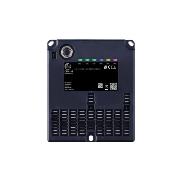
Displays / operating elements
| Display | connection LED, green lights data transmission LED, green flashing |
|---|---|
| Ethernet (ETH0) | 1 LED, green |
| status (SYS0) | 1 LED, multi-colour |
| status (SYS1) | 1 LED, multi-colour |
| status (APP0) | 1 LED, multi-colour programmable |
| status (APP1) | 1 LED, multi-colour programmable |
| status (APP2) | 1 LED, multi-colour programmable |
| no operating system loaded | LED (SYS0), green flashing 5 Hz |
| hardware error fatal error+ | LED (SYS0), red lights |
| system error fatal error | LED (SYS0/SYS1), red lights |
| update | LED (SYS0/SYS1), yellow/green flashing 2 Hz |
| sleep mode | LED (SYS0), blue lights |
| no application | LED, green lights |
| run | LED, green flashing 2 Hz |
| fault | LED, red flashing 10 Hz |
| debug run | LED, yellow flashing 2 Hz |
| debug stop | LED, yellow lights |
| connection | LED, green lights |
| data transmission | LED, green flashing |
Hardware
| Processor | 32-Bit Triple-Core |
|---|---|
| RAM | 2,7 MByte RAM |
| Mass storage | 9 MByte Flash |
| Non-volatile memory | 10 kByte |
| Boot time | ≤ 3 s |
Remarks
| Notes | for use as a safety controller, a separately available licence (CP100S) is required |
|---|---|
| Pack quantity | 1 pcs. |
Electrical connection
| Connector | 1 x M12; coding: D |
|---|
Customer Reviews
Rated 0 out of 5
0 reviews
Rated 5 out of 5
0
Rated 4 out of 5
0
Rated 3 out of 5
0
Rated 2 out of 5
0
Rated 1 out of 5
0
Be the first to review “IFM CR413S” Cancel reply
Reviews
Clear filtersThere are no reviews yet.