")
Fast delivery within 72 Hours
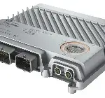
B&R X90CP174.48-S1
Agricultural and forestry machinesConstruction equipmentMunicipal utility vehiclesStationary outdoor applicationsPowerful ARM CPU with 650 MHzMultifunction I/O channelsEthernet, POWERLINK, 3x CAN bus,…
Request for Quote
Shipping & Delivery
-
 Courier delivery
Our courier will deliver to the specified address
5-6 Days
From €20
-
 DHL Courier delivery
DHL courier will deliver to the specified address
2-3 Days
From €40
-
 Warranty 1 year
-
 Free 30-Day returns
Description
Agricultural and forestry machinesConstruction equipmentMunicipal utility vehiclesStationary outdoor applicationsPowerful ARM CPU with 650 MHzMultifunction I/O channelsEthernet, POWERLINK, 3x CAN bus, USBModular expansionThe heart of the X90 mobile system is a controller with a powerful ARM processor and up to 48 multifunction I/O channels. Basic features include connections for CAN, USB, Ethernet and the real-time POWERLINK bus system.The extremely robust die-cast aluminum housing provides space for up to 4 additional expansion boards. These make it possible to add I/O channels or interfaces as well as specific functions such as condition monitoring. The X90 mobile “Safety” variant is also equipped with a safe control system – also known as an X90 SafeLOGIC controller. All 48 multifunction I/Os included as standard can be used by both the standard variant and the X90 SafeLOGIC controller. Input and output signals can thus be read or operated by the standard variant and/or by the safe control system, depending on the wiring. The control lines required for this are linked by a logical AND in a safety-related manner, i.e. an output signal is only enabled if permitted by both the safety application and the standard application.
Specification
| Interfaces | 1x Ethernet, 1x USB, 3x CAN bus, 1x POWERLINK |
|---|---|
| System module | Controller |
| Insulation voltage for GND and housing | 500 Veff |
| B&R ID code | 0xED1F |
| Automation Studio | 4.7 or later |
| Automation Runtime | 4.7 or later |
| Mapp Technology Package | mapp Safety 5.9.0 and later |
| Cooling | Fanless |
| Status indicators | Controller function, operating state, overtemperature, Ethernet, POWERLINK, safety function |
| Module run/error | Yes, using LED status indicator and software |
| CPU function | Yes, using LED status indicator |
| Ethernet | Yes, using LED status indicator |
| Safety function | Yes, using LED status indicator |
| Controller redundancy | No |
| Storage health data support | Yes |
| ACOPOS support | Yes |
| ReACTION-capable I/O channels | No |
| Visual Components support | Yes |
| Max. I/O cycle time | 2 ms |
| Power consumption without interface module and USB | CPU at Ue = 9 / 32 V: 6.3 / 7.8 WI/O at Ue = 9 / 32 V: 0.3 / 3.6 W |
| UN ECE-R10 | Yes |
| CE | Yes |
| UKCA | Yes |
| CRA (Cyber Resilience Act) | In preparation |
| Functional safety | IEC 61508:2010EN 62061:2005/A1:2013EN ISO 13849-1:2015EN ISO 13766-2:2018EN ISO 25119:2018 |
| Note | See section “Safety characteristics” in data sheet. |
| BOOL | 16 |
| INT | 2 |
| UINT | 2 |
| DINT | 2 |
| UDINT | 2 |
| SafeMOTION support | Yes |
| Max. number of SafeMOTION axes | 6, depends on the data width of the modules used |
| Timing precision | Time * 0.05 + Cycle time of the safety application |
| Max. number of SafeNODEs | 10, depends on the data width of the modules used |
| Max. total data width for each direction | 8 bytes |
| Use as Managing SafeDOMAIN | Starting with mapp Safety 5.10.0 and hardware upgrade 2.2.0.0. |
| Use as Connected SafeDOMAIN | Starting with mapp Safety 5.13.0, hardware upgrade 2.3.0.0 and Automation Runtime A4.90 |
| Max. total number of data points for each direction | 4 |
| Max. number of linked Managing SafeDOMAINs | 0.Starting with mapp Safety 5.13.0, hardware upgrade 2.3.0.0 and Automation Runtime A4.90: 1 |
| FB instances | 256 |
| Marker memory | 5120 bytes (0x1400) |
| Stack memory | 4096 bytes,version 2.3.0.0 and later. 8192 bytes |
| Memory for safe input data | 128 bytes, 68 bytes of which are usable for modules,version 2.3.0.0 and later. 512 bytes |
| Memory for safe output data | 64 bytes,version 2.3.0.0 and later. 128 bytes |
| Memory for standard input data | 64 bytes,version 2.3.0.0 and later. 128 bytes |
| Memory for standard output data | 64 bytes,version 2.3.0.0 and later. 128 bytes |
| Marker count | 256,version 2.3.0.0 and later. 512 |
| Max. number of function block types | 64 |
| Max. number of force variables | 8,version 2.3.0.0 and later. 16 |
| Max. number of variable with variable status | 128 |
| Input voltage | 9 to 32 VDC |
| Reset switching threshold | 6.8 V ±5% |
| V_CPU | No, required fuse 5 A slow-blow |
| V_I/O | No, required fuse 10 A slow-blow per connection pin |
| Overvoltage | 48 V ≤5 minutes |
| Overvoltage protection | Load dump pulse A 202 V Ri = 4 Ω |
| Reverse polarity protection | Yes |
| Real-time clock | Resolution 1 s, retention min. 200 hours, typ. 1000 hours at 25°C, precision ±8 ppm over the entire temperature range |
| FPU | Yes |
| Type | CAN bus |
| Clock frequency | 650 MHz |
| Data code | 32 kB |
| Program code | 32 kB |
| L2 cache | 512 kB |
| Integrated I/O processor | Processes I/O data points in the background |
| Option boards | Max. 32 A |
| Remanent variables | 32 kB FRAM, retention >10 years |
| Shortest task class cycle time | 400 µs |
| RAM | 512 MB DDR3 SDRAM |
| Data retention | 10 years |
| Guaranteed | 100 TB |
| Results for 5 years | 54.8 GB/day |
| Guaranteed erase/write cycles | 100,000 |
| Error-correcting code (ECC) | Yes |
| Variant | Current-sourcing/Current-sinking FET, channels can be connected in parallel. |
| Line length | Max. 100 m between 2 stations (segment length) |
| Transfer rate | Max. 1 Mbit/s |
| Physical layer | 100BASE-TX |
| Half-duplex | Yes |
| Full-duplex | No |
| Autonegotiation | Yes |
| Auto-MDI/MDIX | Yes |
| Fieldbus | POWERLINK managing or controlled node |
| Max. output current | 500 mA |
| Connection designation | CAN3 |
| Max. distance | 1000 m |
| Terminating resistor | External 120 Ω must be provided. |
| Quantity | 0 to 16 (11x 4 A and 5x 6 A),depends on the use of the multifunction outputs |
| Functions | Safe digital output:Type C, 4 A nominal current (PWM 4 A), 6 A nominal current (PWM 6 A), source circuit, integrated output protection per channel, central cutoff via relay, error stateDigital output:Safe digital outputs, 4 A nominal current (PWM 4 A), 6 A nominal current (PWM 6 A), sink/source circuit – Configurable per channel, integrated output protection per channel, configurable overload monitoring per channel, central cutoff via relay, parallel connection, current measurement, error state with configurable error filterPWM output:4 A nominal current (PWM 4 A), 6 A nominal current (PWM 6 A), PWM frequency 15 Hz to 4 kHz, sink/source circuit – Configurable per channel, integrated output protection per channel, configurable overload monitoringper channel, central cutoff via relay, parallel connection, current measurement (asynchronous or synchronous to PWM period), configurable load current distribution of PWM outputs, dither.H bridge:4 A nominal current (PWM 4 A), 6 A nominal current (PWM 6 A), PWM frequency 15 Hz to 8 kHz (at load),integrated output protection per channel, configurable overload monitoringper channel, central cutoff via relay, parallel connection, current measurement (asynchronous or synchronous to PWM period), configurable load current distribution of PWM outputs, dither. Digital input:Digital inputs, sink/source circuit configurable per channel, configurable software input filter |
| Nominal voltage | 12 / 24 VDC |
| Input current at 24 VDC | Typ. 1.4 / 2.8 / 3.7 mA, configurable |
| Input circuit | Sink |
| Hardware | MF-DI: 4 μs if switching threshold = 50% supply voltage |
| Software | 10 to 100 ms, configurable |
| Input resistance | MF-DI: Typ. 6.4 / 8.6 / 17.8 kΩ, configurableMF-AI: Typ. 6.5 / 9 / 18 kΩ, configurable |
| Input frequency | MF-DI: Max. 50 kHz |
| Switching threshold | MF-DI: 50% of supply voltageMF-AI: Switching threshold and hysteresis configurable with softwareMF-DO: 14% supply voltageMF-PWM: 14% supply voltage |
| Error detection time | Max. 8 hours |
| Low | <30% of supply voltage |
| High | >60% of supply voltage |
| Input | 0 to 10 V / 0 to 32 V / 0 to 20 mA / 4 to 20 mA / 0 to 50 kΩ / Temperature inputs (Pt1000 characteristic curve) |
| Digital converter resolution | 12-bit |
| Conversion time | MF-PWM: 40 μs |
| Data type | INT |
| Voltage | Sensor power supply 1: 5/10 V Sensor power supply 2: 5 V |
| Current | Sensor power supply 1: Max. 400 mA, accuracy: ±3%Sensor power supply 2: Max. 500 mA, accuracy: ±4% |
| Resistance | 0.0018%/°C |
| Temperature input | 0.027%/°C |
| Measuring current resistance / Temperature input | <1.6 mA |
| Open-circuit detection | From the application |
| Conversion procedure | SAR |
| Input filter | First-order low-pass filter / cutoff frequency of voltage input 350 Hz, current input 200 Hz |
| Gain | MF-PWM: <0.2% |
| Offset | MF-PWM: <0.1% |
| Nonlinearity | <0.2% |
| Input type | 0 to 10 V / 0 to 32 V / 0 to 20 mA |
| Noise | <0.7% |
| Error with sensor internal resistance >1 kΩ | 0 to 20 mA: -0 to 10 V / 0 to 32 V: 1.1% |
| Internal sensor resistance for single-channel use | Max. 200 Ω |
| Single-channel | 0 to 32 V: 24% |
| Dual-channel | 0 to 10 V / 0 to 32 V: 3%0 to 20 mA: 5% |
| Switching voltage | MF-DO, MF-PWM: V_IO -15%MF-PVG, MF-AI (ratiometric output) : V_CPU – 15% |
| Output format | INTMF-PWM: INT 0x8001 to 0x7FFF / 1 LSB = 305 µA |
| Nominal output current | MF-DO: 4 AMF-PWM: 4 A / 6 A |
| Output protection | Thermal shutdown in the event of overcurrent or short circuit, integrated protection for switching inductive loads |
| Diagnostic status | Overload |
| Leakage current when the output is switched off | MF-DO: Typ. 10 μA, max. 4.1 mAMF-PWM: Typ. 20 μA, max. 4.1 mA |
| RDS(on) | MF-DO: 80 mΩMF-PWM: 50 mΩ |
| Residual voltage | <1 V at 4 A nominal current |
| Peak short-circuit current | 50 A (max. 0.2 ms) |
| Resistive load | MF-DO: Max. 250 Hz |
| Inductive load | MF-DO: Load current 4 A: Max. 4 mH (see section “Switching inductive loads”) |
| Braking voltage when switching off inductive loads | MF-DO: Typ. 64 VDC |
| Switching delay | MF-DO: Max. 150 µs |
| Nominal | 9 to 32 VDC |
| Sampling time | MF-DO: 160 μsMF-PWM: 40 μs |
| Current measurement range | MF-PWM: ±10 A |
| Max. gain drift | MF-PWM: <0.04%/°C |
| Max. offset drift | MF-PWM: <0.005%/°C |
| Length of OSSD pulses | <750 µs |
| Max. capacitive load | MF-DO: 4.7 nF |
| Internal capacity | 1.2 mF |
| Supply voltage (permissible range) | 9 to 32 VDC |
| PWM frequency | 15 Hz to 4 kHz |
| Duty cycle | 0 to 100%, resolution 0.16 µs |
| Common mode error | MF-PWM: 0.015%/V |
| Multifunction digital outputs (MF-DO) | Max. 20 A |
| Mainboard | Max. 40 A |
| Complete system | Max. 70 A |
| Inrush current | Up to 500 A for <300 μs |
| Electrical isolation | Ethernet (IF2) and POWERLINK (IF3) isolated from each other and from other interfaces |
| Any | Yes |
| 0 to 2000 m | No limitation |
| Degree of protection per EN 60529 | IP66, IP69K |
| Horizontal mounting orientation | -40 to 85°C housing surface |
| Vertical mounting orientation | -40 to 85°C housing surface |
| Derating | See section “Derating”. |
| Storage | 5 to 95%, non-condensing |
| Transport | 5 to 95%, non-condensing |
| Operation | 5 to 100%, condensing |
| Width | 250 mm |
| Length | 231 mm |
| Height | 44 mm |
| Weight | Max. 2.3 kg |
| Content of delivery | 2x protective covers for unused female M12 connectors |
Reviews
Clear filtersThere are no reviews yet.