")
Fast delivery within 72 Hours
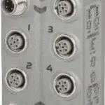
B&R X67UM1352
1 strain gauge input with 24-bit resolutionHigh data output rate (10 to 3,750 Hz)Adjustable gain1 high-side output 24 VDC, 0.5 A1 high-side output 24 VDC, 1.0 A…
Request for Quote
Shipping & Delivery
-
 Courier delivery
Our courier will deliver to the specified address
5-6 Days
From €20
-
 DHL Courier delivery
DHL courier will deliver to the specified address
2-3 Days
From €40
-
 Warranty 1 year
-
 Free 30-Day returns
Description
1 strain gauge input with 24-bit resolutionHigh data output rate (10 to 3,750 Hz)Adjustable gain1 high-side output 24 VDC, 0.5 A1 high-side output 24 VDC, 1.0 A
This module enables the remote connection of a force gauge using a strain gauge with a converter resolution of up to 24-bit. The data rate can be set from 0.26 ms to 100 ms. This module concept requires compensation in the measurement system. This compensation eliminates the absolute uncertainty in the measurement circuit, such as component tolerances, effective bridge voltage or zero point offset. The measurement precision refers to the absolute (compensated) value, which will only change as a result of changes in the operating temperature. The module is also equipped with 4 digital inputs and 2 digital outputs.
Specification
| I/O module |
4 digital inputs, 2 digital outputs, 1 input for full-bridge strain gauge |
|---|---|
| B&R ID code |
0x1CDF |
| Status indicators |
I/O function per channel, supply voltage, bus function |
| Outputs |
Yes, using LED status indicator |
| I/O power supply |
M8, 4-pin |
| X2X Link |
M12, B-coded |
| Inputs/Outputs |
4x M12, A-coded |
| Internal I/O |
1 W |
| X2X Link power supply |
0.75 W |
| CE |
Yes |
| UKCA |
Yes |
| CRA (Cyber Resilience Act) |
In preparation |
| ATEX |
Zone 2, II 3G Ex nA IIA T5 Gc |
| UL |
cULus E115267 |
| HazLoc |
cCSAus 244665 |
| KC |
Yes |
| Nominal voltage |
24 VDC |
| Integrated protective function |
Reverse polarity protection |
| Sensor power supply |
0.5 A summation current |
| Voltage |
4.5 VDC / max. 60 mA |
| Voltage drop for short-circuit protection at 60 mA |
Max. 0.36 VDC |
| Short-circuit proof |
Yes |
| Voltage drop for short-circuit protection at 0.5 A |
Max. 2 VDC |
| Summation current |
Max. 0.5 A |
| Strain gauge factor |
±15.625 to ±125 mV/V, configurable using software |
| Input type |
Differential, used to evaluate a full-bridge strain gauge |
| Digital converter resolution |
24-bit |
| Conversion time |
Depends on the configured data output rate |
| Data output rate |
10 to 3750 samples per second, configurable using software |
| Cutoff frequency |
50 kHz |
| Order |
1 |
| Slope |
20 dB |
| Operating range / Measurement sensor |
75 to 5000 Ω |
| Influence of cable length |
Twisted and shielded conductors, cable length as short as possible, cable routing separate from load circuits, without intermediate terminal to sensor |
| Input protection |
RC protection |
| Input current |
450 nA |
| Common-mode range |
0 to 3 VDC |
| Insulation voltage between input and bus |
500 Veff |
| Gain |
1 to 8, configurable using software |
| Conversion procedure |
Sigma-delta |
| Broken bridge supply line |
Value approaching 0 |
| Broken sensor line |
Value approaching ±final value |
| Valid range of values |
0x7FFF FFFF to 0x8000 0001 |
| Connection |
4-wire connections |
| Short-circuit and overload-proof |
Yes |
| 69 mV/V |
36.4 nV |
| 138 mV/V |
72.8 nV |
| 276 mV/V |
146.0 nV |
| 553 mV/V |
251.0 nV |
| Temperature coefficient |
50 ppm/°C |
| Quantity |
2 |
| Input characteristics per EN 61131-2 |
Type 1 |
| Input voltage |
24 VDC ±25% |
| Input current at 24 VDC |
Typ. 5 mA |
| Input circuit |
Sink |
| Hardware |
<1 ms |
| Software |
– |
| Input resistance |
Typ. 4.27 kΩ |
| Low |
<5 VDC |
| High |
>15 VDC |
| Insulation voltage between channel and bus |
500 Veff |
| Switching voltage |
24 VDC ±25% |
| Output circuit |
Source |
| Output protection |
Thermal shutdown in the event of overcurrent or short circuit, integrated protection for switching inductive loads, reverse polarity protection of the output power supply |
| Actuator power supply |
External |
| Insulation voltage between output and bus |
500 Veff |
| Output 1 |
100 Hz |
| Output 2 |
1 kHz |
| Typical |
15 µs |
| 0 → 1 (90% VOut) |
Max. 160 µs |
| 1 → 0 (90% VOut) |
Max. 50 µs |
| Electrical isolation |
Channel isolated from bus and digital isolated from analog Digital not isolated from I/O power supply |
| Any |
Yes |
| 0 to 2000 m |
No limitation |
| >2000 m |
Reduction of ambient temperature by 0.5°C per 100 m |
| Degree of protection per EN 60529 |
IP67 |
| Operation |
-25 to 60°C |
| Storage |
-40 to 85°C |
| Transport |
-40 to 85°C |
| Width |
53 mm |
| Height |
85 mm |
| Depth |
42 mm |
| Weight |
200 g |
| M8 |
Max. 0.4 Nm |
| M12 |
Max. 0.6 Nm |
Reviews
Clear filtersThere are no reviews yet.