")
Fast delivery within 72 Hours
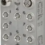
B&R X67DM9331.L12
€ 274,54
5 in stock
8 digital channels, configurable as inputs or outputsOutputs can handle up to 2 ANode number switches for setting the X2X Link addressReplacement of passive distributorsAll outputs with single-channel…
5 in stock
Request for Quote
Shipping & Delivery
-
 Courier delivery
Our courier will deliver to the specified address
5-6 Days
From €20
-
 DHL Courier delivery
DHL courier will deliver to the specified address
2-3 Days
From €40
-
 Warranty 1 year
-
 Free 30-Day returns
Description
8 digital channels, configurable as inputs or outputsOutputs can handle up to 2 ANode number switches for setting the X2X Link addressReplacement of passive distributorsAll outputs with single-channel diagnosticsExtensive additional status information
This module is equipped with 8 digital channels that can be configured either as inputs or outputs. The inputs are designed for a sink circuit, and the outputs are designed for a source circuit. The outputs can be loaded with up to 2 A. The summation current is 8 A.The node number switch for setting the X2X Link address is a unique feature. When modular machine configurations change, it is required, for example, to define certain module groups at a fixed address that is independent of the preceding modules in the line. All subsequent standard modules refer to this offset and use it automatically for addressing purposes.
Specification
| I/O module |
8 digital channels, configurable as inputs or outputs using software |
|---|---|
| Insulation voltage between channel and bus |
500 Veff |
| Nominal voltage |
24 VDC |
| B&R ID code |
0x1B15 |
| Sensor/Actuator current |
0.1 A |
| Summation current |
Max. 0.5 A |
| Status indicators |
I/O function per channel, sensor/actuator power supply per channel, supply voltage, bus function |
| Outputs |
Yes, using LED status indicator and software |
| I/O power supply |
M8, 4-pin |
| Sensor/Actuator power supply |
Max. 12 W |
| X2X Link |
M12, B-coded |
| Inputs/Outputs |
8x M12, A-coded |
| Internal I/O |
1.7 W |
| X2X Link power supply |
0.75 W |
| CE |
Yes |
| UKCA |
Yes |
| CRA (Cyber Resilience Act) |
In preparation |
| ATEX |
Zone 2, II 3G Ex nA IIA T5 Gc |
| UL |
cULus E115267 |
| HazLoc |
cCSAus 244665 |
| KC |
Yes |
| Voltage range |
18 to 30 VDC |
| Integrated protective function |
Reverse polarity protection |
| Voltage |
I/O power supply minus voltage drop for short-circuit protection |
| Voltage drop for short-circuit protection at 0.5 A |
Max. 2 VDC |
| Short-circuit proof |
Yes |
| Input characteristics per EN 61131-2 |
Type 1 |
| Input voltage |
18 to 30 VDC |
| Input current at 24 VDC |
Typ. 4.4 mA |
| Input circuit |
Sink |
| Hardware |
≤70 μs |
| Software |
Default 0 ms, configurable between 0 and 25 ms in 0.2 ms intervals |
| Input resistance |
Typ. 5 kΩ |
| Low |
<5 VDC |
| High |
>15 VDC |
| Variant |
Current-sourcing FET |
| Switching voltage |
I/O power supply minus residual voltage |
| Nominal output current |
2 A |
| Total nominal current |
8 A |
| Output circuit |
Source |
| Output protection |
Thermal shutdown in the event of overcurrent or short circuit, integrated protection for switching inductive loads, reverse polarity protection of the output power supply |
| Diagnostic status |
Output monitoring with 10 ms delay |
| Leakage current when the output is switched off |
5 µA |
| Switching on after overload shutdown |
Approx. 10 ms (depends on the module temperature) |
| Residual voltage |
<0.5 V at 2 A nominal current |
| Peak short-circuit current |
<21 A |
| 0 → 1 |
<250 µs |
| 1 → 0 |
<270 µs |
| Resistive load |
Max. 100 Hz |
| Braking voltage when switching off inductive loads |
50 VDC |
| Electrical isolation |
Channel isolated from bus Channel not isolated from channel |
| Any |
Yes |
| 0 to 2000 m |
No limitation |
| >2000 m |
Reduction of ambient temperature by 0.5°C per 100 m |
| Degree of protection per EN 60529 |
IP67 |
| Operation |
-25 to 60°C |
| Derating |
– |
| Storage |
-40 to 85°C |
| Transport |
-40 to 85°C |
| Width |
53 mm |
| Height |
155 mm |
| Depth |
42 mm |
| Weight |
325 g |
| M8 |
Max. 0.4 Nm |
| M12 |
Max. 0.6 Nm |
Reviews
Clear filtersThere are no reviews yet.