
")
Fast delivery within 72 Hours
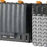
B&R X20CP1381-RT
Intel x86 200 MHz compatible with integrated I/O processorEthernet, POWERLINK with poll-response chaining and onboard USB1 slot for modular interface expansionOnboard reACTION Technology30 digital inp…
Request for Quote
Shipping & Delivery
-
 Courier delivery
Our courier will deliver to the specified address
5-6 Days
From €20
-
 DHL Courier delivery
DHL courier will deliver to the specified address
2-3 Days
From €40
-
 Warranty 1 year
-
 Free 30-Day returns
Description
Intel x86 200 MHz compatible with integrated I/O processorEthernet, POWERLINK with poll-response chaining and onboard USB1 slot for modular interface expansionOnboard reACTION Technology30 digital inputs/outputs and 2 analog inputs integrated in the device1 GB onboard flash drive128 MB DDR3 SDRAMFanlessNo batteryBacked-up real-time clock
The X20 Compact controller series is characterized by 3 integrated I/O modules. The device is equipped with 30 different digital inputs/outputs and 2 analog inputs. 1 analog input can be used for Pt1000 resistance temperature measurement. In addition, the X20CP1381-RT has ultrafast onboard reACTION Technology. reACTION Technology makes it possible to control the integrated I/O channels with response times down to 1 μs. With this new IEC 61131-2 compatible technology, particularly time-critical sub-tasks can be implemented in standard hardware, simultaneously making it possible to reduce costs by optimally reducing the load on the controller and allowing it to be scaled down accordingly. The X20 Compact controller is equipped with an Intel x86 200 MHz compatible processor, 128 MB RAM and 1 GB built-in flash drive. The FRAM for storing remanent variables has 16 kB available. A fanless and battery-free design ensures maintenance-free operation. The controller is equipped with Ethernet, 2x USB and an RS232 interface. In addition, POWERLINK and CAN bus are available as integrated interfaces. For additional fieldbus connections, each controller can be expanded with an interface module from the X20 standard portfolio.
Specification
| Interfaces |
1x RS232, 1x Ethernet, 1x POWERLINK, 2x USB, 1x X2X Link, 1x CAN bus |
|---|---|
| System module |
Controller |
| B&R ID code |
0xE35D |
| Cooling |
Fanless |
| Status indicators |
CPU function, Ethernet, POWERLINK, RS232, CAN bus, CAN bus terminating resistor, PLC power supply, I/O power supply, I/O function per channel |
| Outputs |
Digital outputs: Yes, using LED status indicator and software (output error status) |
| CPU function |
Yes, using LED status indicator |
| CAN bus data transfer |
Yes, using LED status indicator |
| RS232 data transfer |
Yes, using LED status indicator |
| Inputs |
Analog inputs: Yes, using LED status indicator and software |
| Ethernet |
Yes, using LED status indicator |
| I/O power supply |
Yes, using LED status indicator |
| POWERLINK |
Yes, using LED status indicator |
| Supply voltage monitoring |
Yes, using LED status indicator |
| Temperature |
Yes, using software register |
| Terminating resistor |
Integrated in module |
| Controller redundancy |
No |
| ACOPOS support |
Yes |
| ReACTION-capable I/O channels |
Yes |
| Visual Components support |
Yes |
| Power consumption without interface module and USB |
5.1 W |
| Power consumption for X2X Link power supply |
0.8 W |
| Internal I/O |
2.3 W |
| Additional power dissipation caused by actuators (resistive) [W] |
– |
| Type of signal lines |
Shielded lines must be used for all high-speed digital inputs/outputs, line length: Max. 20 m |
| CE |
Yes |
| UKCA |
Yes |
| CRA (Cyber Resilience Act) |
Evaluation ongoing |
| ATEX |
Zone 2, II 3G Ex nA nC IIA T5 Gc |
| UL |
cULus E115267 |
| HazLoc |
cCSAus 244665 |
| DNV |
Temperature: B (0 to 55°C) |
| CCS |
Yes |
| LR |
ENV1 |
| KR |
Yes |
| ABS |
Yes |
| BV |
EC33B |
| Input voltage |
24 VDC -15% / +20% |
| Input current |
Max. 1 A |
| Fuse |
Required line fuse: Max. 10 A, slow-blow |
| Reverse polarity protection |
Yes |
| Nominal output power |
2 W |
| Parallel connection |
Yes |
| Redundant operation |
Yes |
| Nominal output voltage |
24 VDC |
| Permissible contact load |
10 A |
| Real-time clock |
Retention for at least 300 hours, typ. 1000 hours at 25°C, 1 s resolution, -18 to 28 ppm accuracy at 25°C |
| FPU |
Yes |
| Type |
USB 1.1/2.0 |
| Clock frequency |
200 MHz |
| Data code |
16 kB |
| Program code |
16 kB |
| L2 cache |
128 kB |
| Integrated I/O processor |
Processes I/O data points in the background |
| Modular interface slots |
1 |
| Remanent variables |
16 kB FRAM, retention >10 years |
| Shortest task class cycle time |
2 ms |
| Typical instruction cycle time |
0.0419 µs |
| RAM |
128 MB DDR3 SDRAM |
| Data retention |
10 years |
| Guaranteed |
40 TB |
| Results for 5 years |
21.9 GB/day |
| Guaranteed erase/write cycles |
20,000 |
| Error-correcting code (ECC) |
Yes |
| Signal |
CAN bus |
| Variant |
Standard outputs and mixed channels: Current-sourcing FET |
| Max. distance |
1000 m |
| Transfer rate |
Max. 1 Mbit/s |
| Line length |
Max. 100 m between 2 stations (segment length) |
| Physical layer |
100BASE-TX |
| Half-duplex |
Yes |
| Full-duplex |
POWERLINK mode: No / Ethernet mode: Yes |
| Autonegotiation |
Yes |
| Auto-MDI/MDIX |
Yes |
| Fieldbus |
X2X Link master |
| Max. output current |
0.1 A |
| Controller |
SJA 1000 |
| Quantity |
4 standard outputs, 4 high-speed outputs and 4 mixed channels, configuration as input or output using software |
| Nominal voltage |
24 VDC |
| Input current at 24 VDC |
X1 – Standard inputs: Typ. 3.5 mA |
| Input circuit |
Sink |
| Hardware |
Standard inputs and mixed channels: ≤200 μs |
| Software |
Default 1 ms, configurable between 0 and 25 ms in 0.1 ms increments |
| Connection type |
1-wire connections |
| Input resistance |
X1 – Standard inputs: 6.8 kΩ |
| Additional functions |
X2 – High-speed digital inputs: |
| Low |
<5 VDC |
| High |
>15 VDC |
| Encoder inputs |
24 V, asymmetrical |
| Counter size |
32-bit |
| Input frequency |
Max. 10 kHz |
| Evaluation |
1x |
| Encoder power supply |
Module-internal, max. 300 mA |
| Overload characteristics of encoder power supply |
Short-circuit proof, overload-proof |
| Signal form |
Square wave pulse |
| Counter frequency |
250 kHz |
| Possible measurements |
Period measurement, gate measurement, differential time measurement, edge counter, edge times |
| Measurements per module |
Each function up to 2x |
| Timestamp |
1 µs resolution |
| Input |
Resistance measurement with constant current supply for 2-wire connections |
| Input type |
Differential input |
| Voltage |
<0.025% |
| Current |
<0.05% |
| Conversion time |
Only temperature input enabled: 200 µs |
| Data type |
INT |
| Input protection |
Protection against wiring with supply voltage |
| Output of digital value during overload |
Configurable |
| Conversion procedure |
SAR |
| Input filter |
First-order low-pass filter / cutoff frequency 7 Hz |
| Gain |
0.3% (Rev. <C0: 1.93%) |
| Offset |
0.15% (Rev. <C0: 0.32%) |
| DC |
70 dB |
| 50 Hz |
>60 dB |
| Common-mode range |
1 V |
| Crosstalk between channels |
<-70 dB |
| Digital converter resolution |
13-bit |
| Output format |
INT or UINT for resistance measurement |
| Pt1000 |
-200 to 850°C |
| Resistance measurement range |
0.1 to 4000 Ω |
| Temperature sensor resolution |
1 LSB = 0x0005 = 0.16°C |
| Resistance measurement resolution |
1 LSB = 0x0005 = 0.49 Ω |
| Sensor standard |
EN 60751 |
| Linearization method |
Internal |
| Measuring current |
1 mA |
| Permissible input signal |
Short-term max. ±30 V |
| Max. gain drift |
0.023 %/°C |
| Max. offset drift |
0.012%/°C |
| Nonlinearity |
<0.05% |
| Standardized range of values for resistance measurement |
0.1 to 4000.0 Ω |
| Switching voltage |
24 VDC -15% / +20% |
| Nominal output current |
Standard outputs and mixed channels: 0.5 A |
| Total nominal current |
Standard outputs and mixed channels: 4 A |
| Output circuit |
Standard outputs and mixed channels: Source |
| Output protection |
Thermal shutdown in the event of overcurrent or short circuit (see value "Short-circuit peak current") |
| Period duration |
5 to 65535 µs corresponds to 200 kHz to 15 Hz |
| Pulse duration |
0 to 100%, minimum 2.5 µs |
| Resolution for pulse duration |
0.1% of the configured frequency |
| Diagnostic status |
Standard outputs and mixed channels: Output monitoring with 10 ms delay |
| Leakage current when the output is switched off |
Standard outputs and mixed channels: 5 µA |
| RDS(on) |
140 mΩ |
| Residual voltage |
Standard outputs and mixed channels: <0.1 V at nominal current 0.5 A |
| Peak short-circuit current |
Standard outputs and mixed channels: <3 A |
| Switch-on in the event of overload shutdown or short-circuit shutdown |
Standard outputs and mixed channels: Approx. 10 ms (depends on module temperature) |
| 0 → 1 |
Standard outputs and mixed channels: <300 µs |
| 1 → 0 |
Standard outputs and mixed channels: <300 µs |
| Resistive load |
Standard outputs and mixed channels: Max. 500 Hz |
| Inductive load |
See section "Switching inductive loads". |
| Braking voltage when switching off inductive loads |
Standard outputs and mixed channels: Typ. 45 VDC |
| Electrical isolation |
Ethernet (IF2), POWERLINK (IF3) and X2X (IF6) isolated from each other, from other interfaces and from PLC |
| Horizontal |
Yes |
| Vertical |
Yes |
| 0 to 2000 m |
No limitation |
| >2000 m |
Reduction of ambient temperature by 0.5°C per 100 m |
| Degree of protection per EN 60529 |
IP20 |
| Horizontal mounting orientation |
-25 to 60°C |
| Vertical mounting orientation |
-25 to 50°C |
| Derating |
See section "Switching frequency derating for high-speed digital outputs". |
| Storage |
5 to 95%, non-condensing |
| Transport |
5 to 95%, non-condensing |
| Operation |
5 to 95%, non-condensing |
| Note |
X20 end cover plate (right) included in delivery |
| Width |
164 mm |
| Height |
99 mm |
| Depth |
75 mm |
| Weight |
310 g |
Reviews
Clear filtersThere are no reviews yet.