")
Fast delivery within 72 Hours
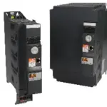
B&R 8I84T200037.01P-1
ACOPOSinverter P84, 3x 200 to 240 V, 0.37 kW, integrated EMC filter and brake chopper, shield plate included in delivery, POWERLINK interface.
Request for Quote
Shipping & Delivery
-
 Courier delivery
Our courier will deliver to the specified address
5-6 Days
From €20
-
 DHL Courier delivery
DHL courier will deliver to the specified address
2-3 Days
From €40
-
 Warranty 1 year
-
 Free 30-Day returns
Description
ACOPOSinverter P84, 3x 200 to 240 V, 0.37 kW, integrated EMC filter and brake chopper, shield plate included in delivery, POWERLINK interface.
Specification
| CE |
Yes |
|---|---|
| UL |
cULus E225616 |
| KC |
Yes |
| Specified on nameplate, 3-phase |
0.37 kW |
| Mains input voltage, 3-phase |
3x 200 VAC -15% to 240 VAC +10% |
| Frequency |
50 to 60 Hz ±5% |
| Apparent power (at 240 VAC) |
1.3 kVA |
| Max. assumed short-circuit current (Isc) (short-circuit current at connection point) |
5 kA |
| At 230 VAC |
1.6 A |
| At 200 VAC |
3.5 A |
| At 240 VAC |
3.1 A |
| Power dissipation at nominal load and nominal clock frequency |
46 W |
| Integrated EMC filter |
Yes |
| Motor cable length per IEC/EN 61800-3 Cat. C1 environment 1 (public power network) |
≤50 m / ≤20 m |
| Motor cable length per IEC/EN 61800-3 Cat. C2 environment 1 (public power network) |
≤100 m / ≤50 m |
| Motor cable length per IEC/EN 61800-3 Cat. C3 environment 2 (industrial power system) |
≤100 m / ≤50 m |
| With add-on filter |
8I0FT012.300-1 |
| At nominal clock frequency (4 kHz or 2.5 kHz with higher inverter power) |
No derating (up to 50°C) |
| Other clock frequencies |
The derating curves are included in the installation instructions, which can be downloaded from the website (www.br-automation.com). |
| Starting at 1000 m above sea level |
1%, per 100 m |
| At 230 VAC, 3-phase |
3 A |
| Max. transient current for 60 s, 3-phase |
4.5 A |
| Max. transient current for 2 s, 3-phase |
4.9 A |
| Output frequency range |
0.5 to 599 Hz |
| Nominal clock frequency |
4 kHz |
| Min. |
3 mA for 24 VDC |
| Max. |
16 kHz |
| Short-term overload torque (typical value) |
170% of the motor's rated torque (typical value at ±10%) for 60 s |
| With braking resistor |
Up to 150% of the rated motor torque |
| Without braking resistor (typical value) |
30% of the rated motor torque |
| Shielded cable |
50 m |
| Non-shielded cable |
100 m |
| Induction motor |
Flux vector control (FVC) with encoder (voltage vector) (current vector) |
| Main protective functions of inverter |
Thermal protection against power stage overheating |
| Motor protection |
Thermal protection integrated in the inverter through continually calculating the l²t value while taking the speed into consideration: |
| Integrated dynamic brake transistors |
Yes |
| Operating ratio for dynamic brake transistors |
The dynamic brake transistor is designed to tolerate the following values: |
| Min. resistance value (external) |
44 Ω |
| Input voltage |
24 VDC (min. 19 V, max. 30 V) |
| Power consumption |
30 W |
| Output voltage 24 VDC |
24 VDC (min. 21 V, max. 27 V) |
| Max. output current at 24 VDC |
200 mA |
| Output voltage 10.5 VDC |
10.5 VDC ±5% |
| Max. output current 10.5 VDC |
10 mA |
| Low |
<5 V |
| High |
>15 V |
| Input - ACOPOSinverter |
Yes |
| Input - Input |
No |
| Quantity |
1 |
| Nominal voltage |
30 VDC / 250 VAC |
| Response time |
≤100 ms |
| Input impedance |
3.5 kΩ |
| Input circuit |
Source or sink |
| Type |
Type 3 |
| Sampling time |
<2 ms ±0.5 ms |
| Voltage |
470 Ω |
| Voltage/Current |
0 to 10 V or 0 to 20 mA |
| Resolution |
10-bit |
| Current |
500 Ω |
| Switching capacity |
Max. 2 A for 250 VAC or 30 VDC with resistive load |
| With resistive load (cos φ = 1 and L/R = 0 ms) |
2 A for 250 VAC or 30 VDC |
| With inductive load (cos φ = 0.4 and L/R = 7 ms) |
1.5 A for 250 VAC or 30 VDC |
| Relay 1 |
1 NO contact and 1 NC contact with a common point |
| Relay 2 |
1 NO contact |
| Response time (max.) |
<7 ms ±0.5 ms |
| Output - ACOPOSinverter |
Yes |
| Output - Output |
No |
| Output |
0 to 10 V or 0 to 20 mA |
| Update time |
<2 ms ±0.5 ms |
| Installation elevation above sea level |
0 to 1000 m |
| Degree of protection per EN 60529 |
Upper part: IP21 and IP41 |
| Ambient temperature |
-10 to 50°C |
| Max. ambient temperature |
Up to 60°C |
| Relative humidity per IEC 60068-2-3 |
5 to 95%, non-condensing |
| Maximum installation elevation |
Up to 3000 m |
| Max. pollution degree per IEC/EN 61800-5-1 |
2 (non-conductive pollution) |
| Ambient conditions per IEC 60721-3-3 |
Class 3C1 and 3S2 |
| Operating position |
Vertical mounting orientation ±10% |
| Storage |
-25 to 70°C |
| Operation |
15 g, 11 ms |
| Width |
130 mm |
| Height |
230 mm |
| Depth |
175 mm |
| Weight |
3 kg |
Reviews
Clear filtersThere are no reviews yet.