


Fast delivery within 72 Hours
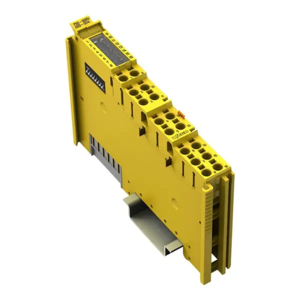
Wago 750-1665/000-004
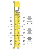
This module (Item No. 750-1665/000-004) has 8 power outputs (O1+ … O8+).The power outputs switch resistive, capacitive and inductive loads according to DC 13 with a nominal current of up to 0.5 A wi…
Request for Quote
Shipping & Delivery
-
 Courier delivery
Our courier will deliver to the specified address
5-6 Days
From €20
-
 DHL Courier delivery
DHL courier will deliver to the specified address
2-3 Days
From €40
-
 Warranty 1 year
-
 Free 30-Day returns
Description
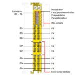
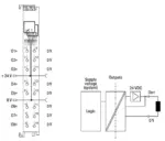
This module (Item No. 750-1665/000-004) has 8 power outputs (O1+ … O8+).The power outputs switch resistive, capacitive and inductive loads according to DC 13 with a nominal current of up to 0.5 A without external additional circuit.The power outputs can be operated unipolar (common potential on one side of the load).Short circuit and 24 V power supply are monitored.The PROFIsafe address is set on the coding switch located on the side, via WAGO-I/O-CHECK or via the Safe Controller Engineering Tool.The module supports PROFIsafe protocols V2.4 and V2.6 (PROFIBUS and PROFINET).Field and system levels are electrically isolated from each other.The individual safe modules can be arranged as required when configuring the fieldbus node.If required (e.g., cable length of the 24 V power supply greater than 3 m), a WAGO filter module or a suitable external filter must be used for the 24 V power supply to protect against surge and burst (per EN 61000-6-7, EN 61326-3-1 and marine applications).For more information, see the manual (German and English).The module (Item No. 75x-1665/000-004) was evaluated by UL in accordance with UL/CSA 61010-1, UL/CSA 61010-2-201 and UL 121201, CSA-C22.2 No. 213.The functional safety assessment according to the above standards was carried out by TÜV Rheinland.
Specification
General technical data
| Protocols | Safe communication via PROFIsafe V2.4 and PROFIsafe V2.6 (PROFINET® and PROFIBUS) |
|---|---|
| Configuration options | Device address adjustable via DIP switch, WAGO Safety Editor 75x or engineering software for the safety controller |
| Indicators | LED (1-8) green/red: Status/error O1+ … O8+; LED (9) red: Module error; LED (10) red/green: Local bus communication; LED (11) red/green: Protocol status; LED (12) red/green: Parameterization |
| Device specification | GSD specification: V2.4 |
| Number of F I/O modules per node (fieldbus coupler/controller) | See information in the manual about the respective fieldbus coupler/controller |
| Device-specific | Channel-granular passivation: Available |
Digital outputs
| Number of digital outputs | 8 |
|---|---|
| Total number of channels (module) | 8 |
| Signal type | Digital |
| Signal type (voltage) | 24 VDC |
| Output characteristic | Two-Channel High-Side with Test Pulses |
| Output characteristics | 0.5 ADC per IEC 61131-2 |
| Output current (per channel) | 0.5 ADC |
| Output current (module) | 4 A |
| Output current | 8 x 0.5 ADC to 40 °C;8 x 0.375 ADC to 55 °C;Note: Observe the permissible mounting positions and the use of distance modules (see “Derating” in the product manual). |
| Output residual current at signal “0” | < 0.5 mA |
| Output protection | Protected and short-circuit-proof per IEC 61131-2 |
| Response threshold (output protection) min. | 0.6 ADC |
| Response threshold (output protection) max. | 1.2 ADC |
| Parallel connection of outputs | Not possible |
| Controlling an IEC 61131‑2-compatible input | Possible; see product manual |
| Response times (max.) (outputs) | See product manual |
| Switching frequency (max.) | 30 Hz; Resistive load |
| Switching frequency (max.) (2) | 0.1 Hz; Inductive load |
| Switching frequency (max.) (3) | 0.1 Hz; Capacitive load |
| Capacitive load for each channel | 10 μF |
| Connection requirement (permissible cable length) (2) | 200 m |
| Connection requirement (permissible cable type) (2) | Shielded or unshielded |
| Read-back time | max. 50 ms |
| Test pulse duration (digital outputs) | 1 … 50 ms; test pulse duration is adaptively adjusted to the actuator |
| Response threshold (output monitoring)min. | 8 VDC (O1+ … O8+) |
| Response threshold (output monitoring) max. | 10 VDC (O1+ … O8+) |
Technical data
| Supply voltage (system) | 5 VDC; via data contacts |
|---|---|
| Current consumption (5 V system supply) | 60 mA |
| Supply voltage (field) | 24 VDC, SELV/PELV (-25 … +20 %); for inductive loads (pilot duty / DC 13); SELV/PELV 24 VDC (−25 ... +30 %) for resistive and general use |
| Current consumption, field supply (module with no external load) | 25 mA |
| Isolation | 500 VDC system voltage / field level (power contacts) |
| Number of incoming power jumper contacts | 2 |
| Number of outgoing power jumper contacts | 2 |
| Current carrying capacity (power jumper contacts) | 10 A |
| Reverse voltage protection | Yes (power jumper contacts) |
Functional Safety
| Achievable safety classes | Digital outputs: Cat. 4/PL e per EN 13849-1; SIL 3 per IEC 61508 / EN 62061 |
|---|---|
| Safety standards | IEC 61508-1 … -7; EN ISO 13849-1; EN 62061 |
| Interface types per ZVEI CB24I (outputs) | Source; C0 |
Connection data
| Connection technology: I/O | 16 x Push-in CAGE CLAMP® (outputs) |
|---|---|
| Connectable conductor materials | Copper |
| Connection type | Output |
| Solid conductor | 0.08 … 1.5 mm² / 28 … 16 AWG |
| Fine-stranded conductor | 0.25 … 1.5 mm² / 22 … 16 AWG |
| Strip length | 8 … 9 mm / 0.31 … 0.35 inches |
Physical data
| Width | 12 mm / 0.472 inches |
|---|---|
| Height | 100 mm / 3.937 inches |
| Depth | 69 mm / 2.717 inches |
| Depth from upper-edge of DIN-rail | 61.8 mm / 2.433 inches |
Mechanical data
| Mounting type | DIN-35 rail |
|---|---|
| Pluggable connector | fixed |
Material data
| Housing material | Polycarbonate; polyamide 6.6 |
|---|---|
| Fire load | 0.819 MJ |
| Weight | 50.3 g |
Environmental requirements
| Ambient temperature (operation) | 0 … +55 °C |
|---|---|
| Ambient temperature (storage) | -40 … +85 °C |
| Protection type | IP20 |
| Protection class | III |
| Overvoltage category | II per IEC 61131-2 |
| Pollution degree | 2 per IEC 61131-2 |
| Operating altitude | 0 … 2000 m / 0 … 6562 ft |
| Mounting position | Horizontal left, horizontal right, horizontal up, vertical top and vertical bottom (up to 40 °C ambient temperature); horizontal left, horizontal right and horizontal up (up to 55 °C ambient temperature) |
| Relative humidity (without condensation) | 95 % |
| Vibration resistance | 4g per IEC 60068-2-6 |
| Shock resistance | 15g per IEC 60068-2-27 |
| EMC immunity to interference | Per EN 61000-6-2; marine applications; EN 61000-6-7 (FS); EN 61326-3-1:2017 |
| EMC emission of interference | per EN 61000-6-4, marine applications, EN 61000-6-3 |
| Exposure to pollutants | per IEC 60068-2-42 and IEC 60068-2-43 |
| Permissible H<sub>2</sub>S contaminant concentration at a relative humidity <lt/> 75 % | 10 ppm |
| Permissible SO<sub>2</sub> contaminant concentration at a relative humidity <lt/> 75 % | 25 ppm |
| Approvals | Marine applications: DNV, E175199 Ordinary Locations, UL E198726 Hazardous Locations: Class I, Div2 ABCD T4 |
Commercial data
| PU (SPU) | 1 pcs |
|---|---|
| Packaging type | Box |
| Country of origin | DE |
| GTIN | 4066966782547 |
| Customs tariff number | 85371098990 |
Product Classification
| ETIM 9.0 | EC001599 |
|---|---|
| ETIM 10.0 | EC001599 |
| ECCN | NO US CLASSIFICATION |
Environmental Product Compliance
| RoHS Compliance Status | Compliant,With Exemption |
|---|---|
| RoHS Exemption | 6(c), 7(a), 7(c)-I, 7(c)-II |
Reviews
Clear filtersThere are no reviews yet.