")
Fast delivery within 72 Hours
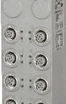
B&R X67DS438A
4 IO-Link channels (Port Class A)Each IO-Link channel can be configured as a digital input or output (SIO mode)Additional digital input per IO-Link connection24 VDC and GND for sensor/actuator supplyN…
Request for Quote
Shipping & Delivery
-
 Courier delivery
Our courier will deliver to the specified address
5-6 Days
From €20
-
 DHL Courier delivery
DHL courier will deliver to the specified address
2-3 Days
From €40
-
 Warranty 1 year
-
 Free 30-Day returns
Description
4 IO-Link channels (Port Class A)Each IO-Link channel can be configured as a digital input or output (SIO mode)Additional digital input per IO-Link connection24 VDC and GND for sensor/actuator supplyNetTime timestamps: IO-Link data
The module is an IO-Link master that allows intelligent sensor and actuators to be connected in accordance to the IO-Link standard. The module can be used to operate up to 4 IO-Link devices. All IO-Link channels can also be operated in SIO mode if desired and thus used as digital inputs or outputs. The module also has 4 additional digital inputs, which can be used independent of the IO-Link channel configuration.
Specification
| I/O module | IO-Link master with 4 IO-Link interfaces |
|---|---|
| B&R ID code | 0xCAAE |
| Status indicators | IO-Link operating state, bus function, module status |
| Module run/error | Yes, using LED status indicator and software |
| IO-Link operating state | Yes, using LED status indicator and software |
| C/Q status | Yes, using LED status indicator and software |
| I/Q status | Yes, using software |
| X2X Link | M12, B-coded |
| Inputs | M12, A-coded |
| I/O power supply | M8, 4-pin |
| Cable type | 4-pin sensor cable, unshielded |
| Cable length | Max. 20 m |
| Line capacitance | Max. 3 nF |
| Loop resistance | Max. 6 Ω |
| Internal I/O | 0.5 W |
| X2X Link power supply | 0.75 W |
| Additional power dissipation caused by actuators (resistive) [W] | – |
| CE | Yes |
| UKCA | Yes |
| CRA (Cyber Resilience Act) | In preparation |
| ATEX | Zone 2, II 3G Ex nA IIA T5 Gc IP67, Ta = 0 – Max. 60°C TÜV 05 ATEX 7201X |
| UL | cULus E115267 Industrial control equipment |
| HazLoc | cCSAus 244665 Process control equipment for hazardous locations Class I, Division 2, Groups ABCD, T5 |
| Nominal voltage | 24 VDC |
| Voltage range | 24 VDC ±25% |
| Integrated protective function | Reverse polarity protection |
| Voltage | I/O power supply minus voltage drop for short-circuit protection |
| Voltage drop for short-circuit protection at 0.5 A | Max. 0.3 V |
| Power consumption | Max. 12 W per IO-Link interface |
| Short-circuit proof | Yes |
| Switch-off delay | Configurable using software |
| Switch-off duration | Configurable using software |
| COM1 | 4.8 kbaud |
| COM2 | 38.4 kbaud |
| COM3 | 230.4 kbaud |
| Max. connection capacity | 22 nF (cable + IO-Link device) |
| Max. load | 96 Ω / 250 mA |
| Data format | 1 start bit, 8 data bits, 1 parity bit (even), 1 stop bit |
| Bus level | 24 VDC (active), 0 VDC (resting voltage) |
| Variant | Bipolar, positive and negative switching |
| Peak short-circuit current | <1.3 A |
| Residual voltage | <0.7 VDC at nominal current 0.25 A |
| Switching voltage | I/O power supply minus voltage drop for short-circuit protection and semiconductor switch |
| Voltage drop on semiconductor switch | Max. 0.5 VDC at 0.25 A |
| 0 → 1 | <10 µs |
| 1 → 0 | <10 µs |
| Overcurrent threshold | Configurable using software |
| Insulation voltage between IO-Link and bus | 500 Veff |
| Nominal output current | 0.25 A |
| Total nominal current | Max. 1 A |
| Output circuit | Sink or source |
| Switching frequency (resistive load) | Max. 500 Hz |
| Output protection | Thermal shutdown in the event of overcurrent or short circuit, integrated protection for switching inductive loads |
| Hardware | ≤60 µs |
| Input circuit | Sink |
| Input voltage | 24 VDC -15% / +20% |
| Input current at 24 VDC | Typ. 3.8 mA |
| Input resistance | Typ. 6.3 kΩ |
| Low | <5 VDC |
| High | >15 VDC |
| Software | Default 1 ms, configurable between 0 and 25.5 ms |
| Insulation voltage between channel and bus | 500 Veff |
| Electrical isolation | Bus isolated from IO-Link |
| Any | Yes |
| 0 to 2000 m | No limitation |
| >2000 m | Reduction of ambient temperature by 0.5°C per 100 m |
| Degree of protection per EN 60529 | IP67 |
| Operation | 5 to 95% |
| Storage | 5 to 95% |
| Transport | 5 to 95% |
| Width | 53 mm |
| Height | 85 mm |
| Depth | 42 mm |
| Weight | 200 g |
| M8 | Max. 0.4 Nm |
| M12 | Max. 0.6 Nm |
Reviews
Clear filtersThere are no reviews yet.