
")
Fast delivery within 72 Hours
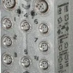
B&R X67BCG321.L12
Fieldbus: EtherCAT16 digital channels, configurable as inputs or outputsAuto-configuration of I/O modulesI/O configuration and firmware update via the fieldbus (FoE)Integrated connection to local expa…
Request for Quote
Shipping & Delivery
-
 Courier delivery
Our courier will deliver to the specified address
5-6 Days
From €20
-
 DHL Courier delivery
DHL courier will deliver to the specified address
2-3 Days
From €40
-
 Warranty 1 year
-
 Free 30-Day returns
Description
Fieldbus: EtherCAT16 digital channels, configurable as inputs or outputsAuto-configuration of I/O modulesI/O configuration and firmware update via the fieldbus (FoE)Integrated connection to local expansion via X2X Link for 250 additional modulesFull support of the modular slice concept via CoE (CANopen over EtherCAT)Configurable I/O cycle (0.2 to 4 ms)Synchronization between the fieldbus and X2X Link
EtherCAT is an Ethernet-based fieldbus developed by Beckhoff. This protocol is suitable for both hard and soft real-time requirements in automation technology. In addition to a ring structure, which becomes logically necessary because of the summation frame telegram used, the EtherCAT technology also physically supports topologies such as line, tree, star (limited) and combinations of these topologies. B&R’s X20BC80G3 (expandable bus controller module) and X20HB88G0 (standalone junction base module) are available for implementing these topologies.EtherCAT slave devices take the data designated for them from a telegram as it is passing through the device. Input data is also added to the telegram as it is passing through. The bus controller allows X2X Link I/O modules to be coupled to EtherCAT and operated on any EtherCAT master system. A transition between IP20 and IP67 protection outside of the control cabinet is possible by arranging X20, X67 or XV modules one after the other as needed at distances up to 100 m.Master systems without FoE (File access over EtherCAT) support require an appropriate configuration tool to transfer the configuration (optional).With multifunction modules, the bus controller supports only the default function model in the event of automatic configuration by the bus controller (see the respective module description). All other function models are supported when configured accordingly in Automation Studio V4.3 or later. Automation Studio kann kostenlos von der B&R Webseite www.br-automation.com heruntergeladen werden. Die Evaluierungslizenz darf unentgeltlich zur Erstellung vollständiger Konfigurationen der Feldbus Bus Controller benützt werden.
Specification
| Bus controller | 0xACF8 |
|---|---|
| Inputs/Outputs | 8x M12, A-coded |
| Insulation voltage between channel and bus | 500 Veff |
| Nominal voltage | 24 VDC |
| Internal I/O module | 0xB402 |
| Sensor/Actuator power supply | Max. 12 W |
| Status indicators | I/O function per channel, supply voltage, bus function |
| Outputs | Yes, using LED status indicator and software |
| I/O power supply | M8, 4-pin |
| Fieldbus | 200 μs |
| X2X Link | 200 μs |
| Power output | 15 W X2X Link power supply for I/O modules |
| Internal I/O | 0.5 W |
| X2X Link power supply | 15% of the power output for X2X Link |
| Additional power dissipation caused by actuators (resistive) [W] | 0.6 |
| CE | Yes |
| UKCA | Yes |
| CRA (Cyber Resilience Act) | In preparation |
| ATEX | Zone 2, II 3G Ex nA IIA T5 Gc IP67, Ta = 0 – Max. 60°C TÜV 05 ATEX 7201X |
| UL | cULus E115267 Industrial control equipment |
| HazLoc | cCSAus 244665 Process control equipment for hazardous locations Class I, Division 2, Groups ABCD, T5 |
| KC | Yes |
| Variant | Current-sourcing FET |
| Line length | Max. 100 m between 2 stations (segment length) |
| Transfer rate | 100 Mbit/s |
| Physical layer | 100BASE-TX |
| Half-duplex | Yes |
| Full-duplex | Yes |
| Autonegotiation | Yes |
| Auto-MDI/MDIX | Yes |
| Hub propagation delay | 750 ns |
| Synchronization between bus systems possible | Yes |
| Voltage range | 18 to 30 VDC |
| Integrated protective function | Reverse polarity protection |
| Voltage | I/O power supply minus voltage drop for short-circuit protection |
| Voltage drop for short-circuit protection at 0.5 A | Max. 2 VDC |
| Summation current | Max. 0.5 A |
| Short-circuit proof | Yes |
| Input characteristics per EN 61131-2 | Type 1 |
| Input voltage | 18 to 30 VDC |
| Input current at 24 VDC | Typ. 4 mA |
| Input circuit | Sink |
| Hardware | ≤10 μs (channels 1 to 4) / ≤70 µs (channels 5 to 16) |
| Software | Default 0 ms, configurable between 0 and 25 ms in 0.2 ms intervals |
| Input resistance | Typ. 6 kΩ |
| Additional functions | 50 kHz event counting, gate measurement |
| Low | <5 VDC |
| High | >15 VDC |
| Quantity | 1 |
| Signal form | Square wave pulse |
| Evaluation | Positive edge – Negative edge |
| Input frequency | Max. 50 kHz |
| Counter 1 | Input 1 |
| Counter 2 | Input 3 |
| Counter frequency | Max. 50 kHz |
| Counter size | 16-bit |
| Internal | 48 MHz, 3 MHz, 187.5 kHz |
| Length of pause between pulses | ≥100 µs |
| Pulse length | ≥20 µs |
| Supported inputs | Input 2 or input 4 |
| Switching voltage | I/O power supply minus residual voltage |
| Nominal output current | 0.5 A |
| Total nominal current | 8 A |
| Output circuit | Source |
| Output protection | Thermal shutdown in the event of overcurrent or short circuit, integrated protection for switching inductive loads, reverse polarity protection of the output power supply |
| Diagnostic status | Output monitoring with 10 ms delay |
| Leakage current when the output is switched off | 5 µA |
| Switching on after overload shutdown | Approx. 10 ms (depends on the module temperature) |
| RDS(on) | 150 mΩ |
| Residual voltage | <0.15 V at 0.5 A nominal current |
| Peak short-circuit current | <12 A |
| 0 → 1 | <400 µs |
| 1 → 0 | <400 µs |
| Resistive load | Max. 100 Hz |
| Inductive load | See section “Switching inductive loads”. |
| Braking voltage when switching off inductive loads | 50 VDC |
| Electrical isolation | Bus isolated from EtherCAT and channel Channel not isolated from channel |
| Any | Yes |
| 0 to 2000 m | No limitation |
| >2000 m | Reduction of ambient temperature by 0.5°C per 100 m |
| Degree of protection per EN 60529 | IP67 |
| Operation | -25 to 60°C |
| Derating | – |
| Storage | -40 to 85°C |
| Transport | -40 to 85°C |
| Width | 53 mm |
| Height | 155 mm |
| Depth | 42 mm |
| Weight | 370 g |
| M8 | Max. 0.4 Nm |
| M12 | Max. 0.6 Nm |
Reviews
Clear filtersThere are no reviews yet.