
")
Fast delivery within 72 Hours
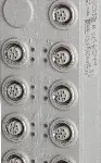
B&R X67BCD321.L12-1
Fieldbus: EtherNet/IPIntegrated 3-port switch (1 internal port) for efficient cablingAuto-configuration of I/O modulesCan be configured by the scanner using configuration assemblyWeb interfaceDHCP-cap…
Request for Quote
Shipping & Delivery
-
 Courier delivery
Our courier will deliver to the specified address
5-6 Days
From €20
-
 DHL Courier delivery
DHL courier will deliver to the specified address
2-3 Days
From €40
-
 Warranty 1 year
-
 Free 30-Day returns
Description
Fieldbus: EtherNet/IPIntegrated 3-port switch (1 internal port) for efficient cablingAuto-configuration of I/O modulesCan be configured by the scanner using configuration assemblyWeb interfaceDHCP-capable16 digital channels, configurable as inputs or outputsM12 connection typeIntegrated connection to local expansions via X2X Link for 252 additional modulesConfigurable I/O cycle (0.5 to 4 ms)Minimum fieldbus cycle time (also requested packet interval or RPI): 1 ms
EtherNet/IP is an Ethernet-based fieldbus. EtherNet/IP was developed by Allen-Bradley (Rockwell Automation) and later transferred to the Open DeviceNet Vendor Association (ODVA) as an open standard. In 1998, a working group at ControlNet International developed a procedure for setting the published Common Industrial Protocol to Ethernet. EtherNet/IP was published in March 2000 as an open industrial automation standard based on this procedure. This bus controller makes it possible to connect X2X Link I/O nodes to EtherNet/IP. The bus controller can be operated via interface module X20IF10D1-1 or by 3rd-party systems with EtherNet/IP scanner functionality. Additional X2X Link I/O nodes (X67 modules or other modules based on X2X Link) can be connected using the integrated X2X Link connection.With multifunction modules, the bus controller supports only the default function model in the event of automatic configuration by the bus controller (see the respective module description). Automation Studio V4.3 or later can be used to easily create configuration files (e.g. EDS files, binary files). All other function models are also supported by transferring configuration data to the bus controller (e.g. using the scanner via a “configuration assembly”). Automation Studio can be downloaded at no cost from the B&R website (www.br-automation.com). The evaluation license is permitted to be used to create complete configurations for fieldbus bus controllers at no cost.
Specification
| Bus controller | 0xDABF |
|---|---|
| Inputs/Outputs | 8x M12, A-coded |
| Insulation voltage between channel and bus | 500 Veff |
| Nominal voltage | 24 VDC |
| Internal I/O module | 0xDACE |
| Sensor/Actuator power supply | Max. 12 W |
| Status indicators | I/O function per channel, supply voltage, bus function |
| Outputs | Yes, using LED status indicator and software |
| I/O power supply | M8, 4-pin |
| Fieldbus | 1 ms |
| X2X Link | 500 μs |
| Power output | 15 W X2X Link power supply for I/O modules |
| Internal I/O | 3.3 W |
| X2X Link power supply | 20.5 W at maximum power output for connected I/O modules |
| CE | Yes |
| UKCA | Yes |
| CRA (Cyber Resilience Act) | In preparation |
| ATEX | Zone 2, II 3G Ex nA IIA T5 Gc IP67, Ta = 0 – Max. 60°C TÜV 05 ATEX 7201X |
| UL | cULus E115267 Industrial control equipment |
| HazLoc | cCSAus 244665 Process control equipment for hazardous locations Class I, Division 2, Groups ABCD, T5 |
| Variant | Current-sourcing FET |
| Line length | Max. 100 m between 2 stations (segment length) |
| Transfer rate | 10/100 Mbit/s |
| Physical layer | 10BASE-T/100BASE-TX |
| Half-duplex | Yes |
| Full-duplex | Yes |
| Autonegotiation | Yes |
| Auto-MDI/MDIX | Yes |
| Synchronization between bus systems possible | No |
| Voltage range | 18 to 30 VDC |
| Integrated protective function | Reverse polarity protection |
| Voltage | I/O power supply minus voltage drop for short-circuit protection |
| Voltage drop for short-circuit protection at 0.5 A | Max. 2 VDC |
| Summation current | Max. 0.5 A |
| Short-circuit proof | Yes |
| Input characteristics per EN 61131-2 | Type 1 |
| Input voltage | 18 to 30 VDC |
| Input current at 24 VDC | Typ. 4 mA |
| Input circuit | Sink |
| Hardware | ≤10 μs (channels 1 to 4) / ≤70 µs (channels 5 to 8) |
| Software | Default 0 ms, configurable between 0 and 25 ms in 0.2 ms intervals |
| Input resistance | Typ. 6 kΩ |
| Additional functions | 50 kHz event counting, gate measurement |
| Low | <5 VDC |
| High | >15 VDC |
| Quantity | 1 |
| Signal form | Square wave pulse |
| Evaluation | Positive edge – Negative edge |
| Input frequency | Max. 50 kHz |
| Counter 1 | Input 1 |
| Counter 2 | Input 3 |
| Counter frequency | Max. 50 kHz |
| Counter size | 16-bit |
| Internal | 48 MHz, 3 MHz, 187.5 kHz |
| Length of pause between pulses | ≥100 µs |
| Pulse length | ≥20 µs |
| Supported inputs | Input 2 or input 4 |
| Switching voltage | I/O power supply minus residual voltage |
| Nominal output current | 0.5 A |
| Total nominal current | 8 A |
| Output circuit | Source |
| Output protection | Thermal shutdown in the event of overcurrent or short circuit, integrated protection for switching inductive loads, reverse polarity protection of the output power supply |
| Diagnostic status | Output monitoring with 10 ms delay |
| Leakage current when the output is switched off | 5 µA |
| Switching on after overload shutdown | Approx. 10 ms (depends on the module temperature) |
| Residual voltage | <0.3 V at 0.5 A nominal current |
| Peak short-circuit current | <12 A |
| 0 → 1 | <400 µs |
| 1 → 0 | <400 µs |
| Resistive load | Max. 100 Hz |
| Inductive load | See section “Switching inductive loads”. |
| Braking voltage when switching off inductive loads | 50 VDC |
| Electrical isolation | Channel isolated from bus EtherNet/IP not isolated from bus and channel not isolated from channel |
| Any | Yes |
| 0 to 2000 m | No limitation |
| >2000 m | Reduction of ambient temperature by 0.5°C per 100 m |
| Degree of protection per EN 60529 | IP67 |
| Operation | -25 to 60°C |
| Derating | – |
| Storage | -40 to 85°C |
| Transport | -40 to 85°C |
| Width | 53 mm |
| Height | 155 mm |
| Depth | 42 mm |
| Weight | 355 g |
| M8 | Max. 0.4 Nm |
| M12 | Max. 0.6 Nm |
Reviews
Clear filtersThere are no reviews yet.