
")
Fast delivery within 72 Hours
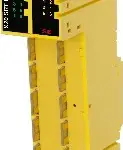
B&R X20SRT402
reACTION Technology module4 high-speed safe digital inputs, sink circuit4 pulse outputsSoftware input filter configurable for each channel2 high-speed safe digital outputs, output type B with 0.2 A, s…
Request for Quote
Shipping & Delivery
-
 Courier delivery
Our courier will deliver to the specified address
5-6 Days
From €20
-
 DHL Courier delivery
DHL courier will deliver to the specified address
2-3 Days
From €40
-
 Warranty 1 year
-
 Free 30-Day returns
Description
reACTION Technology module4 high-speed safe digital inputs, sink circuit4 pulse outputsSoftware input filter configurable for each channel2 high-speed safe digital outputs, output type B with 0.2 A, source circuitSafe reACTION task cycle times starting at 150 µsIntegrated output protection
This reACTION Technology module is equipped with 4 high-speed safe digital inputs and 2 high-speed safe digital outputs. It is designed for a nominal voltage of 24 VDC.The module can be used to read in digital signals and to control actuators in safety-related applications up to PL e or SIL 3.Ultrafast reACTION Technology makes it possible to control internal I/O channels with cycle times down to 150 µs. All commands that can be used for reACTION programs are available as function blocks in special libraries (e.g. AsIORTI). Programming in compliance with IEC 61131-3 requirements takes place in the Function Block Diagram editor in Automation Studio.The module is equipped with filters that are individually configurable for switch-on and switch-off behavior. The module also provides pulse signals for diagnosing the sensor line.The outputs are designed using semiconductor technology so that the safety-related characteristics do not depend on the number of switching cycles. The “high-side high-side” variant (output type B) is required for actuators with reference potential (e.g. enable inputs on frequency inverters). It is important to observe the special notices for the cabling in this case. The safe digital output modules are equipped with an error interlock in the event of network errors.This module is designed for X20 12-pin terminal blocks.
Specification
| I/O module | 4 safe type A digital inputs, 4 pulse outputs, 24 VDC, 2 safe type B2 digital outputs, 24 VDC, 0.2 A, OSSD <10 µs, reACTION Technology |
|---|---|
| B&R ID code | 0xE7EC |
| Automation Studio | 4.2.5 or later |
| Automation Runtime | 4.2 or later |
| SafeDESIGNER | 4.2.2 or later |
| Safety Release | 1.10 or later |
| Mapp Technology Package | mapp Safety 5.7.0 or later |
| Status indicators | I/O function per channel, operating state, module status |
| Module run/error | Yes, using LED status indicator and software |
| Outputs | Yes, using LED status indicator and software |
| Inputs | Yes, using LED status indicator and software |
| ReACTION-capable I/O channels | Yes |
| Scope | Module |
| Function | Programmable |
| Standalone mode | Yes |
| Max. I/O cycle time | 800 µs |
| Bus | 0.4 W |
| Internal I/O | 2.5 W |
| Safe digital HS-HS outputs | 0.4 |
| Pulse outputs | 0.8 |
| Channel - Bus | Yes |
| Channel - Channel | No |
| Type of signal lines | Shielded lines must be used for all signal lines. |
| CE | Yes |
| UKCA | Yes |
| CRA (Cyber Resilience Act) | In preparation |
| Functional safety | EN 50156-1:2004 |
| ATEX | Zone 2, II 3G Ex nA nC IIA T5 Gc IP20, Ta (see X20 user’s manual) FTZÚ 09 ATEX 0083X |
| UL | cULus E115267 Industrial control equipment |
| DNV | In preparation |
| Mission time | Max. 20 years |
| OpenSAFETY wired | Negligible |
| OpenSAFETY wireless | <1*10-14 * Number of openSAFETY packets per hour |
| Proof test interval (PT) | 20 years |
| Category | Cat. 3 if parameter “Disable OSSD = Yes – Warning”, Cat. 4 if parameter “Disable OSSD = No” |
| PL | PL d if parameter “Disable OSSD = Yes – Warning”, PL e if parameter “Disable OSSD = No” |
| DC | >60% if parameter “Disable OSSD = Yes – Warning”, >94% if parameter “Disable OSSD = No” |
| MTTFD per channel | 100 years if parameter “Disable OSSD = Yes – Warning”, 2500 years if parameter “Disable OSSD = No” |
| SIL CL | SIL 2 if parameter “Disable OSSD = Yes – Warning”, SIL 3 if parameter “Disable OSSD = No” |
| SFF | >60% if parameter “Disable OSSD = Yes – Warning”, >90% if parameter “Disable OSSD = No” |
| PFH / PFHd per channel | <5*10-8 if parameter "Disable OSSD = Yes - Warning", <1*10-10 if parameter "Disable OSSD = No" |
| PFD per channel | <1*10-3 if parameter "Disable OSSD = Yes - Warning", <2*10-5 if parameter "Disable OSSD = No" |
| Nominal voltage | 24 VDC |
| Voltage range | 24 VDC -15% / +20% |
| Integrated protective function | Reverse polarity protection |
| Quantity | 4 |
| Variant | Push-Pull |
| Input characteristics per EN 61131-2 | Type 1 |
| Hardware | ≤130 µs |
| Software | Configurable between 0 and 500 ms |
| Input circuit | Sink |
| Input voltage | 24 VDC -15% / +20% |
| Input current at 24 VDC | Min. 2 mA to max. 3.28 mA |
| Input resistance | Min. 7.33 kΩ |
| Error detection time | 1 s |
| Insulation voltage between channel and bus | 500 Veff |
| Low | <5 VDC |
| High | >15 VDC |
| Line length between signal source (pulse output or external signal) and input | Max. 60 m with unshielded line Max. 400 m with shielded line |
| Nominal output current | 50 mA |
| Total nominal current | 200 mA |
| Output protection | Shutdown of individual channels in the event of overload or short circuit |
| Braking voltage when switching off inductive loads | Max. 45 VDC |
| Peak short-circuit current | 0.5 A for 120 µs |
| Leakage current when the output is switched off | 0.1 mA |
| RDS(on) | 80 Ω |
| Switching voltage | I/O power supply minus voltage drop due to RDS(on) |
| Max. switching frequency | See section “Inrush current behavior for output channels”. |
| Test pulse length | Max. 10 µs |
| Max. capacitive load | 100 nF |
| IOUT | <100 µA |
| IGND | <200 mA |
| Short-circuit current | 15 mAeff |
| Horizontal | Yes |
| Vertical | Yes |
| Installation elevation above sea level | 0 to 2000 m, no limitation |
| Degree of protection per EN 60529 | IP20 |
| Horizontal mounting orientation | 0 to 60°C |
| Vertical mounting orientation | 0 to 50°C |
| Derating | See section “Derating”. |
| Storage | 5 to 95%, non-condensing |
| Transport | 5 to 95%, non-condensing |
| Operation | 5 to 95%, non-condensing |
| Note | Order 2x safety-keyed terminal block separately. Order 1x safety-keyed bus module separately. |
| Pitch | 25+0.2 mm |
Reviews
Clear filtersThere are no reviews yet.