


Fast delivery within 72 Hours
Wago 2604-3108
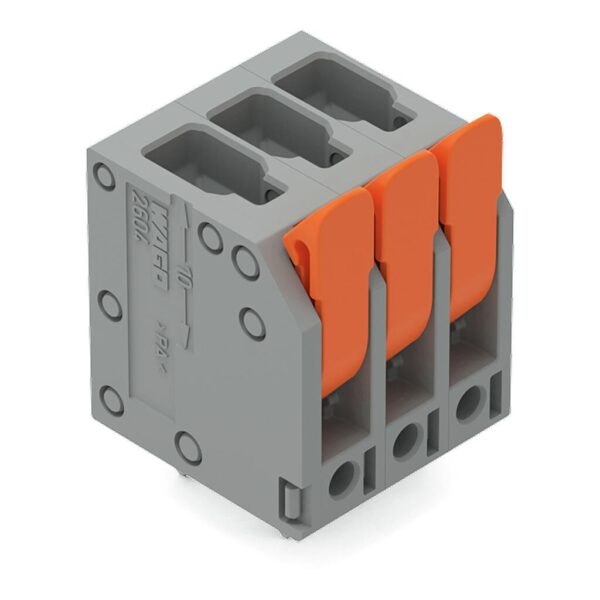
PCB terminal block, 2604 Series, leverQuick and easy connections are guaranteed with this PCB terminal block (item number 2604-3108). You can rely on proven safety with these PCB terminal blocks, perf…
Request for Quote
Shipping & Delivery
-
 Courier delivery
Our courier will deliver to the specified address
5-6 Days
From €20
-
 DHL Courier delivery
DHL courier will deliver to the specified address
2-3 Days
From €40
-
 Warranty 1 year
-
 Free 30-Day returns
Description
PCB terminal block, 2604 Series, leverQuick and easy connections are guaranteed with this PCB terminal block (item number 2604-3108). You can rely on proven safety with these PCB terminal blocks, perfect for a wide variety of applications when designing your devices. This PCB terminal block has a rated voltage of 400 V and can handle currents up to 32 A, making it ideal for high-load applications. Conductors can only be connected to this PCB terminal block if their strip length is between 9 mm and 11 mm. This product features one conductor terminal and utilizes Push-in CAGE CLAMP®. Our Push-in CAGE CLAMP® is a universal, maintenance-free connection solution for all conductor types, offering a key advantage: It allows direct insertion of both solid and fine-stranded conductors with ferrules without needing tools. No preparation is required; for example, crimping the conductor’s ferrule is not necessary. Dimensions: 42.4 x 25.3 x 16.7 mm (width x height x depth). This PCB terminal block is suitable for conductor cross sections ranging from 0.2 mm² to 4 mm². It features one level and eight clamping points that you can use to connect eight potentials / 8 poles. The gray housing is made of polyamide (PA66) for insulation, the clamping spring is made of chrome-nickel spring steel (CrNi), and the contacts are made of electrolytic copper (ECu). Tin is used for coating the contact surfaces. This PCB terminal block is operated with a lever. THT is used to solder the PCB terminal block. The conductor is designed to be inserted at an angle of 90°.. The solder pins measure 0.8 x 1 mm in cross-section and 4 mm in length and are organized over the entire terminal strip (in-line). There are two solder pins per potential.
Specification
Notes
| Variants: | Other pole numbers, Direct marking, Other colors, Other versions (or variants) can be requested from WAGO Sales or configured at https://configurator.wago.com/. |
|---|
Electrical data - Ratings per IEC/EN
| Ratings per | IEC/EN 60664-1 |
|---|---|
| Nominal voltage (III/3) | 320 V |
| Rated impulse withstand voltage (III / 3) | 4 kV |
| Rated voltage (III/2) | 400 V |
| Rated impulse withstand voltage (III/2) | 4 kV |
| Nominal voltage (II/2) | 630 V |
| Rated impulse withstand voltage (II/2) | 4 kV |
| Rated current | 32 A |
| Legend (ratings) | (III / 2) ≙ Overvoltage category III / Pollution degree 2 |
| Ratings per | IEC/EN 60664-1 / IEC/EN 60664-1 / IEC/EN 60664-1 |
| Overvoltage category | III / III / II |
| Pollution degree | 3 / 2 / 2 |
| Nominal voltage | 320 V / 400 V / 630 V |
| Rated impulse withstand voltage | 4 kV / 4 kV / 4 kV |
| Rated current | 32 A / 32 A / 32 A |
Electrical data - Ratings per UL
| Approvals per | UL 1059 |
|---|---|
| Rated voltage UL (Use Group B) | 300 V |
| Rated current UL (Use Group B) | 20 A |
| Rated voltage UL (Use Group D) | 300 V |
| Rated current UL (Use Group D) | 10 A |
| Approvals per | UL 1059 / UL 1059 / UL 1059 |
| Use group | B / C / D |
| Rated voltage | 300 V / 300 V |
| Rated current | 20 A / 10 A |
Electrical data - Ratings per CSA
| Approvals per | CSA |
|---|---|
| Rated voltage CSA (Use Group B) | 300 V |
| Rated current CSA (Use Group B) | 20 A |
| Rated voltage CSA (Use Group D) | 300 V |
| Rated current CSA (Use Group D) | 5 A |
| Approvals per | CSA / CSA / CSA |
| Use group | B / C / D |
| Rated voltage | 300 V / 300 V |
| Rated current | 20 A / 5 A |
Connection data
| Clamping units | 8 |
|---|---|
| Total number of potentials | 8 |
| Number of connection types | 1 |
| Number of levels | 1 |
Connection data - Connection 1
| Connection technology | Push-in CAGE CLAMP® |
|---|---|
| Actuation type | Lever |
| Solid conductor | 0.2 … 4 mm² / 24 … 12 AWG |
| Fine-stranded conductor | 0.2 … 4 mm² / 24 … 12 AWG |
| Fine-stranded conductor; with insulated ferrule | 0.25 … 2.5 mm² |
| Fine-stranded conductor; with uninsulated ferrule | 0.25 … 2.5 mm² |
| Fine-stranded conductor; with twin ferrule | 0.25 … 1.5 mm² |
| Strip length | 9 … 11 mm / 0.35 … 0.43 inches |
| Conductor connection direction to PCB | 90 ° |
| Pole number | 8 |
Physical data
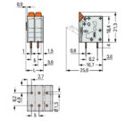
| Pin spacing | 5 mm / 0.197 inches |
|---|---|
| Width | 42.4 mm / 1.669 inches |
| Height | 25.3 mm / 0.996 inches |
| Height from the surface | 21.3 mm / 0.839 inches |
| Depth | 16.7 mm / 0.657 inches |
| Solder pin length | 4 mm |
| Solder pin dimensions | 0.8 x 1 mm |
| Drilled hole diameter with tolerance | 1.3 (+0.1) mm |
PCB contact
| PCB contact | THT |
|---|---|
| Solder pin arrangement | over the entire terminal strip (in-line) |
| Number of solder pins per potential | 2 |
Material data
| Note (material data) | Information on material specifications can be found here |
|---|---|
| Color | gray |
| Material group | I |
| Insulation material (main housing) | Polyamide (PA66) |
| Flammability class per UL94 | V0 |
| Clamping spring material | Chrome-nickel spring steel (CrNi) |
| Contact material | Electrolytic copper (ECu) |
| Contact plating | Tin |
| Fire load | 0.339 MJ |
| Actuator color | orange |
| Weight | 13.2 g |
Environmental requirements
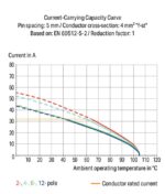
| Limit temperature range | -60 … +105 °C |
|---|---|
| Processing temperature | -35 … +60 °C |
| Continuous operating temperature | -60 … +105 °C |
Environmental requirements - Environmental Testing
| Test specification: <br/>Railway applications –<br/>Rolling stock –<br/>Electronic equipment | DIN EN 50155 (VDE 0115-200):2022-06 |
|---|---|
| Test procedure: <br/>Railway applications – <br/>Rolling stock equipment – <br/>Vibration and shock tests | DIN EN 61373 (VDE 0115-0106):2011-04 |
| Spectrum/Mounting location | Service life test, Category 1, Class A/B |
| Functional test with noise-like oscillations | Test passed according to Section 8 of the standard |
| Frequency | f1 = 5 Hz to f2 = 150 Hz |
| Acceleration | 0.101g (highest test level used for all axes) |
| Test duration per axis | 10 min. |
| Test directions | X, Y and Z axes |
| Monitoring of contact faults and interruptions | Passed |
| Voltage drop measurement before and after each axis | Passed |
| Simulated service life test through increased levels of noise-like oscillations | Test passed according to Section 9 of the standard |
| Frequency | f1 = 5 Hz to f2 = 150 Hz |
| Acceleration | 0.572g (highest test level used for all axes) |
| Test duration per axis | 5 h |
| Test directions | X, Y and Z axes |
| Extended testing: Monitoring of contact faults and interruptions | Passed |
| Extended testing: Voltage drop measurement before and after each axis | Passed |
| Shock test | Test passed according to Section 10 of the standard |
| Shock pulse form | Half sine |
| Acceleration | 5g (highest test level used for all axes) |
| Shock duration | 30 ms |
| Number of shocks (per axis) | 3 pos. und 3 neg. |
| Test directions | X, Y and Z axes |
| Extended testing: Monitoring of contact faults and interruptions | Passed |
| Extended testing: Voltage drop measurement before and after each axis | Passed |
| Vibration and shock stress for rolling stock equipment | Passed |
Commercial data
| PU (SPU) | 40 pcs |
|---|---|
| Packaging type | box |
| Country of origin | PL |
| GTIN | 4066966391053 |
| Customs tariff number | 85369010000 |
Product Classification
| UNSPSC | 39121409 |
|---|---|
| eCl@ss 10.0 | 27-44-04-01 |
| eCl@ss 9.0 | 27-44-04-01 |
| ETIM 9.0 | EC002643 |
| ETIM 10.0 | EC002643 |
| ECCN | NO US CLASSIFICATION |
Environmental Product Compliance
| RoHS Compliance Status | Compliant,No Exemption |
|---|
Reviews
Clear filtersThere are no reviews yet.