")
Fast delivery within 72 Hours
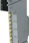
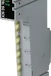
B&R X20DS1319
4 digital input channels4 digital channels, configurable as inputs or outputs1 universal counter pair (2 event counters, AB counters or up/down counters)Linear movement generator (A/B, direction/frequ…
Request for Quote
Shipping & Delivery
-
 Courier delivery
Our courier will deliver to the specified address
5-6 Days
From €20
-
 DHL Courier delivery
DHL courier will deliver to the specified address
2-3 Days
From €40
-
 Warranty 1 year
-
 Free 30-Day returns
Description
4 digital input channels4 digital channels, configurable as inputs or outputs1 universal counter pair (2 event counters, AB counters or up/down counters)Linear movement generator (A/B, direction/frequency) with up to 2 reference pulsesSSI absolute encoderNetTime timestamp: Input data, target position, position change, edge change, counter change
This module is a multifunction digital signal processor module. It can be used extremely flexibly for a wide variety of tasks involving digital signal processing or digital signal generation. Two primary example applications include controlling stepper output stages with pulse and direction signals or using as encoder emulation. In this application, for example, frequency inverters or servo axes with the speed follow function can follow a real or virtual master axis. An additional essential feature is the module’s integrated timestamp function. It allows counter ramps curves to be generated virtually independently of bus cycle times during encoder emulation, for example. Only the target counter value and moment when it should be reached are transferred. The module automatically generates the corresponding counter values at the appropriate time, precisely in microsecond resolution and independently of the bus clock.
Specification
| I/O module | 4 digital input channels, 4 digital channels configurable as inputs or outputs, 1 universal counter pair (2 event counters, AB counter or up/down counter), linear movement generator (A/B, direction/frequency) with up to two reference pulses, SSI absolute encoder, relative or absolute moments of input edges with μs resolution, time-triggered I/O, I/O oversampling |
|---|---|
| B&R ID code | 0x2547 |
| Status indicators | I/O function per channel, operating state, module status |
| Module run/error | Yes, using LED status indicator and software |
| Outputs | Yes, using LED status indicator |
| Bus | 0.01 W |
| Internal I/O | 1.5 W |
| Additional power dissipation caused by actuators (resistive) [W] | – |
| Type of signal lines | Shielded lines must be used for all signal lines. |
| CE | Yes |
| UKCA | Yes |
| CRA (Cyber Resilience Act) | In preparation |
| ATEX | Zone 2, II 3G Ex nA nC IIA T5 Gc IP20, Ta (see X20 user’s manual) FTZÚ 09 ATEX 0083X |
| UL | cULus E115267 Industrial control equipment |
| HazLoc | cCSAus 244665 Process control equipment for hazardous locations Class I, Division 2, Groups ABCD, T5 |
| DNV | Temperature: B (0 to 55°C) Humidity: B (up to 100%) Vibration: B (4 g) EMC: B (bridge and open deck) |
| CCS | Yes |
| LR | ENV1 |
| KR | Yes |
| ABS | Yes |
| BV | EC33B Temperature: 5 – 55°C Vibration: 4 g EMC: Bridge and open deck |
| KC | Yes |
| Quantity | Up to 4, configuration as input or output using software |
| Encoder outputs | 24 V, asymmetrical (A/B, direction/frequency) |
| Counter size | 16/32-bit |
| Nominal voltage | 24 VDC |
| Input voltage | 24 VDC -15% / +20% |
| Input current at 24 VDC | Approx. 1.3 mA |
| Input circuit | Sink |
| Hardware | ≤2 µs |
| Software | – |
| Input resistance | 18.4 kΩ |
| Additional functions | Clock for SSI absolute encoder, linear movement generator |
| Input frequency | Max. 100 kHz |
| Low | <5 VDC |
| High | >15 VDC |
| Overload characteristics of encoder power supply | Short-circuit proof, overload-proof |
| Insulation voltage between channel and bus | 500 Veff |
| Max. transfer rate | 125 kbit/s |
| Encoder power supply | Module-internal, max. 600 mA |
| Operating modes | 2x event counter, up/down counter, AB counter |
| Encoder inputs | 24 V, asymmetrical |
| AB counter | 4x |
| Event counters | 2x |
| Up/Down counter | 2x |
| Signal form | Square wave pulse |
| Variant | Push / Pull / Push-Pull |
| Switching voltage | 24 VDC -15% / +20% |
| Nominal output current | 0.1 A |
| Total nominal current | 0.4 A |
| Output circuit | Sink and/or source |
| Output protection | Thermal shutdown in the event of overcurrent or short circuit, integrated protection for switching inductive loads |
| Diagnostic status | Output monitoring |
| Leakage current when the output is switched off | Max. 25 µA |
| Residual voltage | <0.9 V at 0.1 A nominal current |
| Peak short-circuit current | <10 A |
| Switch-on in the event of overload shutdown or short-circuit shutdown | Approx. 10 ms (depends on the module temperature) |
| 0 → 1 | <2 µs |
| 1 → 0 | <2 µs |
| Resistive load | Max. 125 kHz |
| Inductive load | See section “Switching inductive loads”. |
| Braking voltage when switching off inductive loads | Switching voltage + 0.6 VDC |
| Electrical isolation | Channel isolated from bus Channel not isolated from channel |
| Horizontal | Yes |
| Vertical | Yes |
| 0 to 2000 m | No limitation |
| >2000 m | Reduction of ambient temperature by 0.5°C per 100 m |
| Degree of protection per EN 60529 | IP20 |
| Horizontal mounting orientation | -25 to 60°C |
| Vertical mounting orientation | -25 to 50°C |
| Derating | – |
| Storage | 5 to 95%, non-condensing |
| Transport | 5 to 95%, non-condensing |
| Operation | 5 to 95%, non-condensing |
| Note | Order 1x terminal block X20TB12 separately. Order 1x bus module X20BM11 separately. |
| Pitch | 12.5+0.2 mm |
Reviews
Clear filtersThere are no reviews yet.