")
Fast delivery within 72 Hours
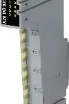
B&R X20DO8332-1
8 digital outputs with 2 ASource circuit1-wire connectionsPower supply integrated in the moduleIntegrated output protection
This module is equipped with 8…
Request for Quote
Shipping & Delivery
-
 Courier delivery
Our courier will deliver to the specified address
5-6 Days
From €20
-
 DHL Courier delivery
DHL courier will deliver to the specified address
2-3 Days
From €40
-
 Warranty 1 year
-
 Free 30-Day returns
Description
8 digital outputs with 2 ASource circuit1-wire connectionsPower supply integrated in the moduleIntegrated output protection
This module is equipped with 8 outputs for 1-wire connections. The outputs are designed for a source circuit. The nominal output current is 2 A. The output power supply is fed directly into the module. An additional power supply module is therefore not necessary. There is no connection between the module and the I/O power supply potential on the bus module.
Specification
| I/O module | 8 digital outputs 24 VDC for 1-wire connections |
|---|---|
| B&R ID code | 0xF321 |
| Status indicators | I/O function per channel, operating state, module status |
| Module run/error | Yes, using LED status indicator and software |
| Outputs | Yes, using LED status indicator and software (output error status) |
| Supply voltage monitoring | Yes, using LED status indicator and software (output error status) |
| Bus | 0.26 W |
| Internal I/O | – |
| External I/O | 0.81 W |
| Additional power dissipation caused by actuators (resistive) [W] | +0.336 |
| CE | Yes |
| UKCA | Yes |
| CRA (Cyber Resilience Act) | In preparation |
| UL | cULus E115267 Industrial control equipment |
| Variant | Current-sourcing FET |
| Number of output groups | 2 |
| Nominal voltage | 24 VDC |
| Switching voltage | 24 VDC -15% / +20% |
| Nominal output current | 2 A |
| Total nominal current | 8 A |
| Connection type | 1-wire connections |
| Output circuit | Source |
| Output protection | Thermal shutdown in the event of overcurrent or short circuit (see value “Short-circuit peak current”) Internal freewheeling diode for switching inductive loads (see section “Switching inductive loads”) Reverse polarity protection of supply voltage |
| Supply | External |
| Fuse | Required line fuse: Max. 10 A, slow-blow |
| Diagnostic status | Output monitoring with 18 ms delay |
| Leakage current when the output is switched off | 5 µA |
| RDS(on) | 21 mΩ |
| Peak short-circuit current | 90 A for 200 µs |
| Switch-on in the event of overload shutdown or short-circuit shutdown | 300 ms |
| 0 → 1 | <300 µs |
| 1 → 0 | <300 µs |
| Resistive load | Max. 500 Hz |
| Inductive load | See section “Switching inductive loads”. |
| Braking voltage when switching off inductive loads | Typ. 64 VDC |
| Insulation voltage between channel and bus | 500 Veff |
| Additional functions | Outputs can be connected in parallel to increase the output current. |
| Electrical isolation | Channel isolated from bus and I/O power supply |
| Horizontal | Yes |
| Vertical | Yes |
| 0 to 2000 m | No limitation |
| >2000 m | Reduction of ambient temperature by 0.5°C per 100 m |
| Degree of protection per EN 60529 | IP20 |
| Horizontal mounting orientation | -25 to 60°C |
| Vertical mounting orientation | -25 to 50°C |
| Derating | See section “Derating”. |
| Storage | 5 to 95%, non-condensing |
| Transport | 5 to 95%, non-condensing |
| Operation | 5 to 95%, non-condensing |
| Note | Order 1x terminal block X20TB12 separately. Order 1x bus module X20BM11 separately. |
| Pitch | 12.5+0.2 mm |
Reviews
Clear filtersThere are no reviews yet.