


Fast delivery within 72 Hours
Wago 231-202/008-000
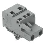
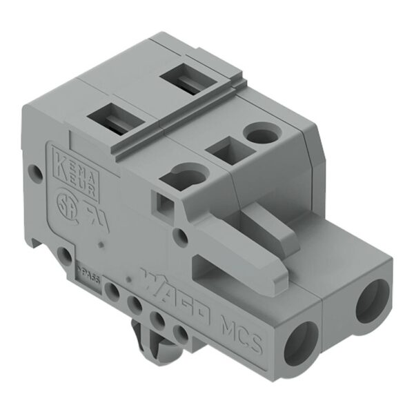
Female connector, 231 Series, CAGE CLAMP®Enjoy error-free electrical installations with this female connector (item number 231-202/008-000). Strip lengths must be between 8 and 9 mm when connecting c…
Request for Quote
Shipping & Delivery
-
 Courier delivery
Our courier will deliver to the specified address
5-6 Days
From €20
-
 DHL Courier delivery
DHL courier will deliver to the specified address
2-3 Days
From €40
-
 Warranty 1 year
-
 Free 30-Day returns
Description
Female connector, 231 Series, CAGE CLAMP®Enjoy error-free electrical installations with this female connector (item number 231-202/008-000). Strip lengths must be between 8 and 9 mm when connecting conductors to this female connector. This product features one conductor terminal and utilizes CAGE CLAMP®. Our CAGE CLAMP® connection offers a proven and maintenance-free way to connect all types of conductors. You do not need to prepare the conductor in any way, such as crimping ferrules. The dimensions are (14 x 18.8 x 26.45) mm (width x height x depth). Depending on the conductor type, this female connector is suitable for conductor cross sections ranging from 0.08 mm² to 2.5 mm².Tin is used for coating the contact surfaces.
Specification
Notes
| Safety Information | The MCS – MULTI CONNECTION SYSTEM includes connectors without breaking capacity in accordance with DIN EN 61984. When used as intended, these connectors must not be connected/disconnected when live or under load.When used as intended, these connectors must not be connected/disconnected when live or under load. The circuit design should ensure header pins, which can be touched, are not live when unmated. |
|---|---|
| Variants: | Gold-plated or partially gold-plated contact surfaces, Other versions (or variants) can be requested from WAGO Sales or configured at https://configurator.wago.com/. |
Electrical data - Ratings per IEC/EN
| Ratings per | IEC/EN 60664-1 |
|---|---|
| Nominal voltage (III/3) | 500 V |
| Rated impulse withstand voltage (III / 3) | 6 kV |
| Rated voltage (III/2) | 630 V |
| Rated impulse withstand voltage (III/2) | 6 kV |
| Nominal voltage (II/2) | 1000 V |
| Rated impulse withstand voltage (II/2) | 6 kV |
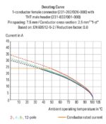
| Rated current | 16 A |
| Legend (ratings) | (III / 2) ≙ Overvoltage category III / Pollution degree 2 |
| Ratings per | IEC/EN 60664-1 / IEC/EN 60664-1 / IEC/EN 60664-1 |
| Overvoltage category | III / III / II |
| Pollution degree | 3 / 2 / 2 |
| Nominal voltage | 500 V / 630 V / 1000 V |
| Rated impulse withstand voltage | 6 kV / 6 kV / 6 kV |
| Rated current | 16 A / 16 A / 16 A |
Electrical data - Ratings per UL
| Approvals per | UL 1059 |
|---|---|
| Rated voltage UL (Use Group B) | 300 V |
| Rated current UL (Use Group B) | 15 A |
| Rated voltage UL (Use Group D) | 300 V |
| Rated current UL (Use Group D) | 10 A |
| Approvals per | UL 1059 / UL 1059 / UL 1059 |
| Use group | B / C / D |
| Rated voltage | 300 V / 300 V |
| Rated current | 15 A / 10 A |
Electrical data - Ratings per UL 1977
| Rated voltage (UL 1977) | 600 V |
|---|---|
| Rated current UL 1977 | 15 A |
| Approvals per | UL 1977 |
| Rated voltage | 600 V |
| Rated current | 15 A |
Electrical data - Ratings per CSA
| Approvals per | CSA |
|---|---|
| Rated voltage CSA (Use Group B) | 300 V |
| Rated current CSA (Use Group B) | 15 A |
| Rated voltage CSA (Use Group D) | 300 V |
| Rated current CSA (Use Group D) | 10 A |
| Approvals per | CSA / CSA / CSA |
| Use group | B / C / D |
| Rated voltage | 300 V / 300 V |
| Rated current | 15 A / 10 A |
Connection data
| Clamping units | 2 |
|---|---|
| Total number of potentials | 2 |
| Number of connection types | 1 |
| Number of levels | 1 |
Connection data - Connection 1
| Connection technology | CAGE CLAMP® |
|---|---|
| Actuation type | Operating tool |
| Actuation direction 1 | Operation parallel to conductor entry |
| Actuation direction 2 | Operation perpendicular to conductor entry |
| Solid conductor | 0.08 … 2.5 mm² / 28 … 12 AWG |
| Fine-stranded conductor | 0.08 … 2.5 mm² / 28 … 12 AWG |
| Fine-stranded conductor; with insulated ferrule | 0.25 … 1.5 mm² |
| Fine-stranded conductor; with uninsulated ferrule | 0.25 … 2.5 mm² |
| Strip length | 8 … 9 mm / 0.31 … 0.35 inches |
| Pole number | 2 |
| Conductor entry direction to mating direction | 0 ° |
Physical data
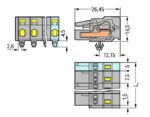
| Pin spacing | 7.5 mm / 0.295 inches |
|---|---|
| Width | 14 mm / 0.551 inches |
| Height | 18.8 mm / 0.74 inches |
| Height from the surface | 14.3 mm / 0.563 inches |
| Depth | 26.45 mm / 1.041 inches |
| Drilled hole diameter for snap-in mounting foot with tolerance | 3.5 (+0.1) mm |
Mechanical data
| Variable coding | Yes |
|---|---|
| Housing sheet thickness | 0.6 … 1.2 mm / 0.024 … 0.047 inches |
| Mounting type | Snap-in foot |
| Mounting type | Panel mounting |
| Anti-rotation protection | Yes |
Plug-in connection
| Contact type (pluggable connector) | Female connector/socket |
|---|---|
| Connector (connection type) | for conductor |
| Mismating protection | No |
| Plugging without loss of pin spacing | No |
| Locking of plug-in connection | none |
Material data
| Note (material data) | Information on material specifications can be found here |
|---|---|
| Color | gray |
| Material group | I |
| Insulation material (main housing) | Polyamide (PA66) |
| Flammability class per UL94 | V0 |
| Clamping spring material | Chrome-nickel spring steel (CrNi) |
| Contact material | Copper alloy |
| Contact plating | Tin |
| Fire load | 0.068 MJ |
| Weight | 4.1 g |
Environmental requirements
| Limit temperature range | -60 … +100 °C |
|---|---|
| Processing temperature | -35 … +60 °C |
Environmental requirements - Environmental Testing
| Test specification: <br/>Railway applications –<br/>Rolling stock –<br/>Electronic equipment | DIN EN 50155 (VDE 0115-200):2022-06 |
|---|---|
| Test procedure: <br/>Railway applications – <br/>Rolling stock equipment – <br/>Vibration and shock tests | DIN EN 61373 (VDE 0115-0106):2011-04 |
| Spectrum/Mounting location | Service life test, Category 1, Class A/B |
| Functional test with noise-like oscillations | Test passed according to Section 8 of the standard |
| Frequency | f1 = 5 Hz to f2 = 150 Hz |
| Acceleration | 0.101g (highest test level used for all axes) |
| Test duration per axis | 10 min. |
| Test directions | X, Y and Z axes |
| Monitoring of contact faults and interruptions | Passed |
| Voltage drop measurement before and after each axis | Passed |
| Simulated service life test through increased levels of noise-like oscillations | Test passed according to Section 9 of the standard |
| Frequency | f1 = 5 Hz to f2 = 150 Hz |
| Acceleration | 0.572g (highest test level used for all axes) |
| Test duration per axis | 5 h |
| Test directions | X, Y and Z axes |
| Extended testing: Monitoring of contact faults and interruptions | Passed |
| Extended testing: Voltage drop measurement before and after each axis | Passed |
| Shock test | Test passed according to Section 10 of the standard |
| Shock pulse form | Half sine |
| Acceleration | 5g (highest test level used for all axes) |
| Shock duration | 30 ms |
| Number of shocks (per axis) | 3 pos. und 3 neg. |
| Test directions | X, Y and Z axes |
| Extended testing: Monitoring of contact faults and interruptions | Passed |
| Extended testing: Voltage drop measurement before and after each axis | Passed |
| Vibration and shock stress for rolling stock equipment | Passed |
Commercial data
| Product Group | 3 (Multi Conn. System) |
|---|---|
| PU (SPU) | 100 pcs |
| Packaging type | box |
| Country of origin | DE |
| GTIN | 4044918374729 |
| Customs tariff number | 85366990990 |
Product Classification
| UNSPSC | 39121409 |
|---|---|
| eCl@ss 10.0 | 27-44-03-09 |
| eCl@ss 9.0 | 27-44-03-09 |
| ETIM 9.0 | EC002638 |
| ETIM 10.0 | EC002638 |
| ECCN | NO US CLASSIFICATION |
Environmental Product Compliance
| RoHS Compliance Status | Compliant,No Exemption |
|---|
Reviews
Clear filtersThere are no reviews yet.