
")
Fast delivery within 72 Hours
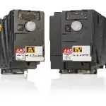
B&R 8I66T400750.00-000
Base device for ACOPOSinverter P66 and P64new, 3 x 380 to 500 V, 7.5 kW, integrated EMC filter and brake chopper, shield plate included in deliveryOrder number – ACOPOSinverter P66: 8I66T400750.0P-000…
Request for Quote
Shipping & Delivery
-
 Courier delivery
Our courier will deliver to the specified address
5-6 Days
From €20
-
 DHL Courier delivery
DHL courier will deliver to the specified address
2-3 Days
From €40
-
 Warranty 1 year
-
 Free 30-Day returns
Description
Base device for ACOPOSinverter P66 and P64new, 3 x 380 to 500 V, 7.5 kW, integrated EMC filter and brake chopper, shield plate included in deliveryOrder number – ACOPOSinverter P66: 8I66T400750.0P-000: Inverter with POWERLINK communication card8I66T400750.0X-000: Inverter with X2X Link communication card8I66T400750.0C-000: Inverter with integrated CANopen interface Order number – ACOPOSinverter P64new: 8I64T400750.0X-000: Inverter with X2X Link communication card
Specification
| CE | Yes |
|---|---|
| UKCA | Yes |
| CRA (Cyber Resilience Act) | In preparation |
| UL | cULus E225616 Power conversion equipment |
| KC | Yes |
| Specified on nameplate | 7.5 kW (10 HP) |
| Mains input voltage | 3x 380 VAC -15% to 500 VAC +10% |
| Frequency | 50 to 60 Hz ±5% |
| Apparent power (at 500 VAC) | 17 kVA |
| Max. assumed short-circuit current (Isc) (short-circuit current at connection point) | 22 kA |
| Inrush current | 27.6 A |
| At 380 VAC | 25.5 A |
| At 500 VAC | 19.6 A |
| Power dissipation at nominal load and nominal clock frequency | 262 W |
| Integrated EMC filter | No |
| Motor cable length per IEC/EN 61800-3 Cat. C2 environment 1 (public power network) | 100 m |
| Motor cable length per IEC/EN 61800-3 Cat. C3 environment 2 (industrial power system) | 150 m |
| Motor cable length per IEC/EN 61800-3 Cat. C1 environment 1 (public power network) | 20 m |
| Nominal output current | 17 A |
| At nominal clock frequency (4 kHz) | No derating (up to 50°C) |
| Other clock frequencies | The derating curves are included in the installation instructions, which can be downloaded from the website (www.br-automation.com). |
| Starting at 1000 m above sea level | 1%, per 100 m |
| Max. transient current for 60 s | 25.5 A |
| Output frequency range | 0.1 to 599 Hz |
| Nominal clock frequency | 4 kHz |
| Min. | 2 kHz |
| Max. | 16 kHz |
| With braking resistor | Up to 170% of the rated motor torque |
| Shielded cable | 50 m |
| Non-shielded cable | 100 m |
| Induction motor | Sensorless vector control: 1. Voltage controlled with constant torque → standard mode 2. Voltage controlled with variable torque → energy saving mode e.g. for fans and pumps Sensorless slip control: 1. With V/f characteristic curve for constant torque → standard mode 2. With V/f characteristic curve for constant torque (up to 6 f-ranges) → Custom mode for special applications 3. With V/f characteristic curve for quadratically increasing torque → Energy-saving mode, e.g. for fans and pumps |
| Synchronous motor | Sensorless vector control: 1. Voltage controlled with constant torque → standard mode |
| Main protective functions of inverter | Thermal protection against power stage overheating Protection against short circuits between motor phases, overcurrent between output phases and ground, overvoltages on the DC bus, exceeding the speed limit. Safety function for: Overvoltage and undervoltage of the mains supply, mains phase failure with 3-phase power supply |
| Integrated dynamic brake transistors | Yes |
| Min. resistance value (external) | 27 Ω |
| Input voltage | 24 VDC (-15%/+20%) |
| Current | 800 Ω |
| Output voltage 24 VDC | 24 VDC (-15%/+20%) |
| Max. output current at 24 VDC | 100 mA |
| Output voltage 10 VDC | 10 VDC (-0%/+10%) |
| Max. output current at 10 VDC | 10 mA |
| Type | Type 3 |
| Quantity | 1 |
| Nominal voltage | 30 VDC / 250 VAC |
| Input circuit | Source or sink |
| Switching threshold | Sink: >19 V (position 0), <13 V (position 1) Source: 11 V (position 1) |
| Input - ACOPOSinverter | Yes |
| Input - Input | No |
| Sampling time | 2 ms |
| Max. input frequency | 20 kHz |
| Input impedance | 1.5 kΩ |
| Current consumption | 16 mA |
| Nonlinearity | ±0.3% |
| Basic accuracy | At 25°C: ±1% At -10 to 60°C: ±2% |
| Voltage | 470 Ω |
| Resolution | 10-bit |
| Max. voltage | 30 VDC |
| Output circuit | Source or sink |
| Max. current | 100 mA |
| Switching current range | Min. switching current: 5 mA at 24 VDC Max. switching current: R1 at cos φ = 1: 3 A at 250 VAC / 4 A at 30 VDC R2 at cos φ = 1: 5 A R1 and R2 at cos φ = 0.4: 2 A |
| Relay 1 | 1 changeover contact |
| Relay 2 | 1 normally open contact |
| Output - ACOPOSinverter | Yes |
| Output - Output | No |
| Response time (max.) | 2 ms |
| Output | 0 to 10 V or 0 to 20 mA |
| Update time | 2 ms |
| Power dissipation relative to continuous apparent power | IE2 (10, 25): 0.6% (3x 380 VAC), 0.5% (3x 500 VAC) IE2 (50, 25): 0.6% (3x 380 VAC), 0.5% (3x 500 VAC) IE2 (10, 50): 0.8% (3x 380 VAC), 0.7% (3x 500 VAC) IE2 (50, 50): 0.8% (3x 380 VAC), 0.7% (3x 500 VAC) IE2 (90, 50): 0.9% (3x 380 VAC), 0.7% (3x 500 VAC) IE2 (10, 100): 1.5% (3x 380 VAC), 1.3% (3x 500 VAC) IE2 (50, 100): 1.5% (3x 380 VAC), 1.2% (3x 500 VAC) IE2 (90, 100): 1.9% (3x 380 VAC), 1.4% (3x 500 VAC) |
| Nominal losses in standby mode | 8 W (3x 380 VAC), 10 W (3x 500 VAC) |
| Degree of protection per EN 61800-5-1 | IP20 |
| Relative humidity per IEC 60068-2-3 | 5 to 95%, non-condensing No dripping water |
| Maximum installation elevation | ≤1000 m without derating 1000 to 3000 m with Derating |
| Max. pollution degree per IEC/EN 61800-5-1 | 2 (non-conductive pollution) |
| Ambient conditions per IEC 60721-3-3 | Class 3C3 and 3S2 |
| Operating position | Vertical mounting orientation ±10° |
| Operation | -10 to 50°C without derating 50 to 60°C with derating |
| Storage | -25 to 70°C |
| Max. vibration resistance | 1 gn 13 to 200 Hz EN/IEC 60068-2-6 1.5 mm peak to peak 2 to 13 Hz EN/IEC 60068-2-6 |
| Width | 150 mm |
| Height | 308 mm |
| Height without shield plate | 232 mm |
| Depth | 178 mm |
| Weight | 3.6 kg |
Reviews
Clear filtersThere are no reviews yet.