


Fast delivery within 72 Hours
Wago 2004-1311/1000-401
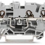
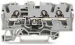
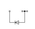
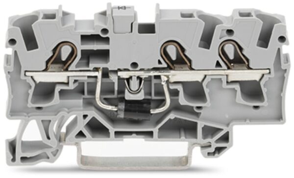
Component terminal block with diode, 2004 Series, Push-in CAGE CLAMP®Connect conductors quickly and safely with this component terminal block with diode (item number 2004-1311/1000-401). Conductors sh…
Request for Quote
Shipping & Delivery
-
 Courier delivery
Our courier will deliver to the specified address
5-6 Days
From €20
-
 DHL Courier delivery
DHL courier will deliver to the specified address
2-3 Days
From €40
-
 Warranty 1 year
-
 Free 30-Day returns
Description
Component terminal block with diode, 2004 Series, Push-in CAGE CLAMP®Connect conductors quickly and safely with this component terminal block with diode (item number 2004-1311/1000-401). Conductors should only be connected to this component terminal block with diode if their strip length is between 11 and 13 mm . Featuring conductor terminals along with Push-in CAGE CLAMP®, this connector is highly versatile. Our Push-in CAGE CLAMP® is a universal, maintenance-free connection solution for all conductor types, featuring a winning design: both solid and fine-stranded conductors with ferrules can be directly inserted without the need for tools or any preparation, such as crimping the ferrule. This component terminal block with diode is suitable for conductor cross sections ranging from 0.5 mm² to 6 mm².
Specification
Electrical data - General information
| Nominal voltage | 250 V |
|---|---|
| Reverse voltage | 1,000 V |
| Continuous current (max.) | 1.5 A |
| Number/type of diode/LED | with 1N5408 diode |
| Wiring direction | Front-entry wiring |
Connection data
| Clamping units | 3 |
|---|---|
| Total number of potentials | 1 |
| Number of levels | 1 |
Connection data - Connection 1
| Connection technology | Push-in CAGE CLAMP® |
|---|---|
| Actuation type | Operating tool |
| Connectable conductor materials | Copper |
| Nominal cross-section | 4 mm² |
| Solid conductor | 0.5 … 6 mm² / 20 … 10 AWG |
| Solid conductor; push-in termination | 1.5 … 6 mm² / 14 … 10 AWG |
| Fine-stranded conductor | 0.5 … 6 mm² / 20 … 10 AWG |
| Fine-stranded conductor; with insulated ferrule | 0.5 … 4 mm² / 20 … 12 AWG |
| Fine-stranded conductor; with ferrule; push-in termination | 1.5 … 4 mm² / 18 … 12 AWG |
| Note (conductor cross-section) | Depending on the conductor characteristic, a conductor with a smaller cross-section can also be inserted via push-in termination. |
| Strip length | 11 … 13 mm / 0.43 … 0.51 inches |
| Wiring direction | Front-entry wiring |
Physical data
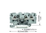
| Width | 6.2 mm / 0.244 inches |
|---|---|
| Height | 65.5 mm / 2.579 inches |
| Depth from upper-edge of DIN-rail | 32.9 mm / 1.295 inches |
Mechanical data
| Mounting type | DIN-35 rail |
|---|---|
| Marking level | Center/side marking |
Material data
| Note (material data) | Information on material specifications can be found here |
|---|---|
| Color | gray |
| Material group | I |
| Insulation material (main housing) | Polyamide (PA66) |
| Flammability class per UL94 | V0 |
| Fire load | 0.157 MJ |
| Weight | 9.7 g |
Environmental requirements
| Processing temperature | -35 … +85 °C |
|---|---|
| Continuous operating temperature | -60 … +105 °C |
Environmental requirements - Environmental Testing
| Test specification: <br/>Railway applications –<br/>Rolling stock –<br/>Electronic equipment | DIN EN 50155 (VDE 0115-200):2022-06 |
|---|---|
| Test procedure: <br/>Railway applications – <br/>Rolling stock equipment – <br/>Vibration and shock tests | DIN EN 61373 (VDE 0115-0106):2011-04 |
| Spectrum/Mounting location | Service life test, Category 1, Class A/B |
| Functional test with noise-like oscillations | Test passed according to Section 8 of the standard |
| Frequency | f1 = 5 Hz to f2 = 150 Hz |
| Acceleration | 0.101g (highest test level used for all axes) |
| Test duration per axis | 10 min. |
| Test directions | X, Y and Z axes |
| Monitoring of contact faults and interruptions | Passed |
| Voltage drop measurement before and after each axis | Passed |
| Simulated service life test through increased levels of noise-like oscillations | Test passed according to Section 9 of the standard |
| Frequency | f1 = 5 Hz to f2 = 150 Hz |
| Acceleration | 0.572g (highest test level used for all axes) |
| Test duration per axis | 5 h |
| Test directions | X, Y and Z axes |
| Extended testing: Monitoring of contact faults and interruptions | Passed |
| Extended testing: Voltage drop measurement before and after each axis | Passed |
| Shock test | Test passed according to Section 10 of the standard |
| Shock pulse form | Half sine |
| Acceleration | 5g (highest test level used for all axes) |
| Shock duration | 30 ms |
| Number of shocks (per axis) | 3 pos. und 3 neg. |
| Test directions | X, Y and Z axes |
| Extended testing: Monitoring of contact faults and interruptions | Passed |
| Extended testing: Voltage drop measurement before and after each axis | Passed |
| Vibration and shock stress for rolling stock equipment | Passed |
Commercial data
| Product Group | 22 (TOPJOB S) |
|---|---|
| PU (SPU) | 50 pcs |
| Packaging type | box |
| Country of origin | DE |
| GTIN | 4050821230977 |
| Customs tariff number | 85369010000 |
Product Classification
| UNSPSC | 39121410 |
|---|---|
| eCl@ss 10.0 | 27-14-11-27 |
| eCl@ss 9.0 | 27-14-11-27 |
| ETIM 9.0 | EC000903 |
| ETIM 10.0 | EC000903 |
| ECCN | NO US CLASSIFICATION |
Environmental Product Compliance
| RoHS Compliance Status | Compliant,No Exemption |
|---|---|
| SCIP notification number (Austria) | 8dc8d47b-f191-4bdc-8953-5a97f4d68cc4 |
| SCIP notification number (Belgium) | 559b6efa-01f2-4158-819c-04a4ab892448 |
| SCIP notification number (Bulgaria) | aaf295d4-9e5b-4992-b95a-20d3cbd1101b |
| SCIP notification number (Czech Republic) | 0cfe348d-42e9-447c-92c7-8a770f266376 |
| SCIP notification number (Denmark) | d6e0f4cb-84a2-4777-bf8a-f6a498e798c5 |
| SCIP notification number (Finland) | acfffe07-2230-4ff1-b745-16c3f7ae1fd2 |
| SCIP notification number (France) | baa47e4d-50bd-48bc-b5ef-c3656fa5f14b |
| SCIP notification number (Germany) | ca365395-2aea-493c-b03c-83999a21a875 |
| SCIP notification number (Hungary) | 71d76c85-fc40-40d3-aec8-a2c9dd6f886e |
| SCIP notification number (Italy) | 20b0f0d1-a6d9-47be-b60e-91e8d8e4a309 |
| SCIP notification number (Netherlands) | 2febe39b-31f6-424f-bc24-1ee20afb5645 |
| SCIP notification number (Poland) | c7479101-997e-4690-a18c-97f78cd58c1a |
| SCIP notification number (Romania) | 413fe567-c747-4a51-9a4f-8e3981d8124a |
| SCIP notification number (Sweden) | e8b14449-0ab3-401e-97f7-310107411f3a |
Reviews
Clear filtersThere are no reviews yet.