


Shipping & Delivery
-
 Courier delivery
Our courier will deliver to the specified address
5-6 Days
From €20
-
 DHL Courier delivery
DHL courier will deliver to the specified address
2-3 Days
From €40
-
 Warranty 1 year
-
 Free 30-Day returns
Description
Long ranges and a wide temperature range
Reliable measurements even in precipitation, fog, dust and dirt
Simultaneous detection of distance and speed
Operating modes can be set in accordance with the specific application
Intuitive set-up and visualisation of the measured data using the ifm Vision Assistant software
Specification
Product characteristics
| Communication interface | IO-Link |
|---|---|
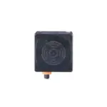
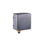
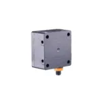
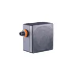
| Housing | rectangular |
| Dimensions[mm] [mm] | 80 x 80 x 45 |
| Electrical design | PNP/NPN; (parameterisable) |
| Output function | normally open / normally closed; (parameterisable) |
Application
| Radio approval for | Argentina; India |
|---|
Electrical data
| Operating voltage[V] [V] | 10...30 DC; (to SELV/PELV ; energy-limited circuits according to IEC/UL 61010-1 3rd ed. cl. 9.4) |
|---|---|
| Current consumption[mA] [mA] | < 300; (mean value: 150 mA) |
| Power consumption[W] [W] | 21; (maximum) |
| Protection class | III |
| Reverse polarity protection | yes |
| Max. power-on delay time[ms] [ms] | 1000 |
| Operating frequency [GHz] | 76...77 |
| Mean radiated power EIRP [dBm] | 24 |
Inputs / outputs
| Total number of inputs and outputs | 3 |
|---|
Inputs
| Inputs | IN1 activation/deactivation of the radar |
|---|---|
| IN1 | activation/deactivation of the radar |
Outputs
| Total number of outputs | 2 |
|---|---|
| Output signal | OUT1 switching signal; IO-Link OUT2 switching signal; analogue signal |
| OUT1 | switching signal; IO-Link |
| OUT2 | switching signal; analogue signal |
| Short-circuit protection | yes |
| Type of short-circuit protection | pulsed |
| Overload protection | yes |
| Analogue current output[mA] [mA] | 4...20, invertible; (scalable) |
| Max. load[Ω] [Ω] | 500; (< 250 Ω: Ub 16...30 V DC; 250...500 Ω: Ub 18...30 V DC) |
| Analogue voltage output[V] [V] | 0...10, invertible; (scalable) |
| Min. load[Ω] [Ω] | 2000 |
| Electrical design | PNP/NPN; (parameterisable) |
| Output function | normally open / normally closed; (parameterisable) |
| Max. voltage drop switching output DC[V] [V] | 2.5 |
| Permanent current rating of switching output DC[mA] [mA] | 200 |
Detection zone
| Range[m] [m] | 0.35...50; (referred to E23013) |
|---|---|
| Angle of aperture cylindrical[°] [°] | horizontal 40 vertical 20 |
| horizontal | 40 |
| vertical | 20 |
Measuring/setting range
| Measuring range[m] [m] | 0.35...50; (see diagram:) |
|---|---|
| Sampling rate[Hz] [Hz] | 20...100 |
Accuracy / deviations
| Hysteresis[mm] [mm] | 5; (parameterisable) |
|---|---|
| Temperature coefficient analogue output[% of the span / 10 K] [% of the span / 10 K] | ± 0,1 |
| Repeatability analogue output [% of the span] | < 0,1 |
| Linearity error of analogue output [% of the span] | ± 0,15 |
| Precision analogue output [% of the span] | ± 0,2 (in addition to the accuracy specifications in the further data section) |
Software / programming
| Parameter setting options | only via IO-Link |
|---|
Interfaces
| Communication interface | IO-Link |
|---|---|
| Transmission type | COM3 (230,4 kBaud) |
| IO-Link revision | 1.1 |
| SDCI standard | IEC 61131-9 |
| Profiles | BLOB Binary Large Object transfer Common - I&D Identification and Diagnosis Function Locator Function ProductURI |
| BLOB | Binary Large Object transfer |
| Common - I&D | Identification and Diagnosis |
| Function | ProductURI |
| SIO mode | yes |
| Required master port type | A |
| Min. process cycle time[ms] [ms] | 3.2 |
| IO-Link process data (cyclical) | distance 32 speed 32 Power 8 RCS 8 sensor inclination 1 device status 4 binary switching information 4 |
| distance | 32 |
| speed | 32 |
| Power | 8 |
| RCS | 8 |
| sensor inclination | 1 |
| device status | 4 |
| binary switching information | 4 |
| IO-Link functions (acyclical) | application specific tag; operating hours counter; number of trigger events; internal temperature; ROI setting |
| Supported DeviceIDs | default 1518 |
| default | 1518 |
Operating conditions
| Ambient temperature[°C] [°C] | -40...80 |
|---|---|
| Note on ambient temperature | without using the analogue output: -40...85 °C |
| Storage temperature[°C] [°C] | -40...85 |
| Protection | IP 65; IP 66; IP 67; IP 69K; (with mounted connectors or protective caps) |
Tests / approvals
| EMC | DIN EN 61000-4-2 ESD 4 kV CD / 8 kV AD DIN EN 61000-4-3 HF radiated 10 V/m DIN EN 61000-4-4 Burst 2 kV DIN EN 61000-4-6 HF conducted 10 V DIN EN 61000-6-2 immunity / industrial environments EN 55032 emission Class A |
|---|---|
| DIN EN 61000-4-2 ESD | 4 kV CD / 8 kV AD |
| DIN EN 61000-4-3 HF radiated | 10 V/m |
| DIN EN 61000-4-4 Burst | 2 kV |
| DIN EN 61000-4-6 HF conducted | 10 V |
| DIN EN 61000-6-2 | immunity / industrial environments |
| EN 55032 emission | Class A |
| Impact resistance | IEC 62262 IK06 (1J) |
| IEC 62262 | IK06 (1J) |
| Vibration resistance | DIN EN 60068-2-6 Fc 10 g 10 frequency cycles, 1 octave/minute, in 3 axes |
| DIN EN 60068-2-6 Fc | 10 g 10 frequency cycles, 1 octave/minute, in 3 axes |
| Shock resistance | DIN EN 60068-2-27 Ea 50 g 11 ms half-sine; 10 shocks each in every direction along the 3 coordinate axes |
| DIN EN 60068-2-27 Ea | 50 g 11 ms half-sine; 10 shocks each in every direction along the 3 coordinate axes |
| Continuous shock resistance | DIN EN 60068-2-29 Eb 40 g 6 ms half-sine; 4,000 shocks each in every direction along the 3 coordinate axes |
| DIN EN 60068-2-29 Eb | 40 g 6 ms half-sine; 4,000 shocks each in every direction along the 3 coordinate axes |
| Fast temperature change | DIN EN 60068-2-14 Na TA = -40°C; TB = 85°C; t1 = 30 min; t2 = < 30 s; 300 cycles |
| DIN EN 60068-2-14 Na | TA = -40°C; TB = 85°C; t1 = 30 min; t2 = < 30 s; 300 cycles |
| Salt spray test | DIN EN 60068-2-11 Ka 8 test cycles |
| DIN EN 60068-2-11 Ka | 8 test cycles |
| Electrical safety | DIN EN 61010-2-201 electric shock / electrical supply only via SELV/PELV circuits |
| DIN EN 61010-2-201 | electric shock / electrical supply only via SELV/PELV circuits |
| MTTF[years] [years] | 54 |
Mechanical data
| Weight[g] [g] | 414.55 |
|---|---|
| Housing | rectangular |
| Mounting | flush mountable |
| Dimensions[mm] [mm] | 80 x 80 x 45 |
| Materials | housing: PA; radome: PEI; Sealing: HNBR |
Displays / operating elements
| Display | switching status 2x LED, yellow operation 1x LED, green errors 1x LED, red |
|---|---|
| switching status | 2x LED, yellow |
| operation | 1x LED, green |
| errors | 1x LED, red |
Remarks
| Pack quantity | 1 pcs. |
|---|
Electrical connection
| Connector | 1 x M12; coding: A |
|---|
Customer Reviews
Rated 0 out of 5
0 reviews
Rated 5 out of 5
0
Rated 4 out of 5
0
Rated 3 out of 5
0
Rated 2 out of 5
0
Rated 1 out of 5
0
Be the first to review “IFM R1D204” Cancel reply

Reviews
Clear filtersThere are no reviews yet.