


Fast delivery within 72 Hours
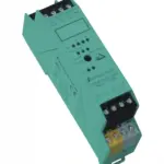
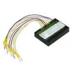
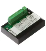
Pepperl Fuchs VBA-4E4A-CB1-ZEJ/E2J
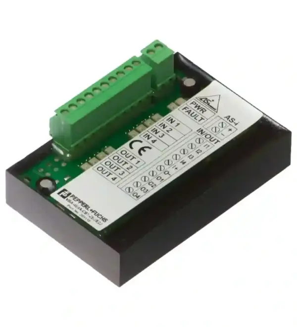
AS-Interface printed circuit board module. Printed circuit board module, 4 inputs/4 outputs. Node type: A/B node. AS-Interface specification: V3.0. Required gateway specification: V3.0. UL File Number…
Request for Quote
Shipping & Delivery
-
 Courier delivery
Our courier will deliver to the specified address
5-6 Days
From €20
-
 DHL Courier delivery
DHL courier will deliver to the specified address
2-3 Days
From €40
-
 Warranty 1 year
-
 Free 30-Day returns
Description
AS-Interface printed circuit board module. Printed circuit board module, 4 inputs/4 outputs. Node type: A/B node. AS-Interface specification: V3.0. Required gateway specification: V3.0. UL File Number: E223772. LED FAULT: error display; LED redred: communication error or address is 0red flashing: overload of outputs. LED PWR: AS-Interface voltage; LED green. LED IN: switching state (input); 4 LED yellow. LED OUT: Switching state (output); 4 LED yellow. Rated operating voltage: 26.5 … 31.6 V from AS-Interface. Rated operating current: ≤ 30 mA (without sensors) / max. 180 mA. Protection class: III. Surge protection: Ue: Over voltage category III, safe isolated power supplies (PELV). Number/Type: 4 inputs for 2- or 3-wire sensors (PNP), DC. Supply: from AS-Interface. Voltage: 21 … 31 V. Input current: 5 mA (typically). Switching point: according to EN 61131-2 Typ 1. 0 (unattenuated)≤ 0.5 mA1 (attenuated)≥ 2 mA: . 0 (unattenuated): ≤ 0.5 mA. 1 (attenuated): ≥ 2 mA. Signal delay: < 2 ms (input/AS-Interface). Number/Type: 4 electronic outputs, PNP. Supply: from AS-Interface. Voltage: 21 … 31 V. Current: ≤ 100 mA per output, ≤ 140 mA total. Electromagnetic compatibility: . Directive 2014/30/EUEN 61326-1:2013 EN 61000-6-4:2007 EN 62026-2:2015: . Directive 2014/30/EU: EN 61326-1:2013 EN 61000-6-4:2007 EN 62026-2:2015. Degree of protection: EN 60529:2000. Fieldbus standard: EN 50295:1999, IEC 62026-2:2015. Input: EN 61131-2:2015. Emitted interference: EN 61000-6-4:2007. AS-Interface: EN 62026-2:2013. Noise immunity: EN 61326-1:2013. Profile: S-7.A.7. IO code: 7. ID code: A. ID1 code: 7. ID2 code: 7. Data bits (function via AS-Interface): InputOutput. D0 IN1 OUT1D1 IN2 OUT2D2 IN3 OUT3D3 IN4 OUT4: . D0: IN1 OUT1. D1: IN2 OUT2. D2: IN3 OUT3. D3: IN4 OUT4. Parameter bits (programmable via AS-i): function. P0Communication monitoringP0 = 0 monitoring = off, the outputs maintain the status if communication failsP0 = 1 monitoring = on, i.e. if communication fails, the outputs are deenergised (default settings)P1Input filterP1 = 0 input filter on, pulse suppression ≤ 2 msP1 = 1 input filter off (default settings)P2Synchronous modeP2 = 0 synchronous mode onP2 = 1 synchronous mode off (default settings)P3not used: . P0: Communication monitoringP0 = 0 monitoring = off, the outputs maintain the status if communication failsP0 = 1 monitoring = on, i.e. if communication fails, the outputs are deenergised (default settings). P1: Input filterP1 = 0 input filter on, pulse suppression ≤ 2 msP1 = 1 input filter off (default settings). P2: Synchronous modeP2 = 0 synchronous mode onP2 = 1 synchronous mode off (default settings). P3: not used. Ambient temperature: -25 … 60 °C (-13 … 140 °F). Storage temperature: -40 … 85 °C (-40 … 185 °F). Relative humidity: 85 % , noncondensing. Climatic conditions: For indoor use only. Altitude: ≤ 2000 m above MSL. Pollution degree: 2. Connection: screw terminals, removable rated connection capacity:rigid/flexible (with and without wire-end ferrules): 0.25 mm2 … 1.5 mm2In case of wire end ferrule with plastic sleeve: 0.25 mm2 … 0.5 mm2On connection of multiple conductors when using two conductors with the same cross section:Flexible with twin wire end ferrule:. Mass: 90 g. Dimensions: . Height29 mmWidth51 mmLength76 mm: . Height: 29 mm. Width: 51 mm. Length: 76 mm. Tightening torque of clamping screws: 0.22 … 0.25 Nm
Specification
General specifications
| Node type | A/B node |
|---|---|
| AS-Interface specification | V3.0 |
| Required gateway specification | V3.0 |
| UL File Number | E223772 |
Indicators/operating means
| LED FAULT | error display; LED redred: communication error or address is 0red flashing: overload of outputs |
|---|---|
| LED PWR | AS-Interface voltage; LED green |
| LED IN | switching state (input); 4 LED yellow |
| LED OUT | Switching state (output); 4 LED yellow |
Electrical specifications
| Rated operating voltage | 26.5 ... 31.6 V from AS-Interface |
|---|---|
| Rated operating current | ≤ 30 mA (without sensors) / max. 180 mA |
| Protection class | III |
| Surge protection | Ue: Over voltage category III, safe isolated power supplies (PELV) |
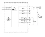
Input
| Number/Type | 4 inputs for 2- or 3-wire sensors (PNP), DC |
|---|---|
| Supply | from AS-Interface |
| Voltage | 21 ... 31 V |
| Input current | 5 mA (typically) |
| Switching point | according to EN 61131-2 Typ 1 |
| 0 (unattenuated)≤ 0.5 mA1 (attenuated)≥ 2 mA | |
| 0 (unattenuated) | ≤ 0.5 mA |
| 1 (attenuated) | ≥ 2 mA |
| Signal delay | < 2 ms (input/AS-Interface) |
Output
| Number/Type | 4 electronic outputs, PNP |
|---|---|
| Supply | from AS-Interface |
| Voltage | 21 ... 31 V |
| Current | ≤ 100 mA per output, ≤ 140 mA total |
Directive conformity
| Electromagnetic compatibility | |
|---|---|
| Directive 2014/30/EUEN 61326-1:2013 EN 61000-6-4:2007 EN 62026-2:2015 | |
| Directive 2014/30/EU | EN 61326-1:2013 EN 61000-6-4:2007 EN 62026-2:2015 |
Standard conformity
| Degree of protection | EN 60529:2000 |
|---|---|
| Fieldbus standard | EN 50295:1999, IEC 62026-2:2015 |
| Input | EN 61131-2:2015 |
| Emitted interference | EN 61000-6-4:2007 |
| AS-Interface | EN 62026-2:2013 |
| Noise immunity | EN 61326-1:2013 |
Programming instructions
| Profile | S-7.A.7 |
|---|---|
| IO code | 7 |
| ID code | A |
| ID1 code | 7 |
| ID2 code | 7 |
| Data bits (function via AS-Interface) | InputOutput |
| D0 IN1 OUT1D1 IN2 OUT2D2 IN3 OUT3D3 IN4 OUT4 | |
| D0 | IN1 OUT1 |
| D1 | IN2 OUT2 |
| D2 | IN3 OUT3 |
| D3 | IN4 OUT4 |
| Parameter bits (programmable via AS-i) | function |
| P0Communication monitoringP0 = 0 monitoring = off, the outputs maintain the status if communication failsP0 = 1 monitoring = on, i.e. if communication fails, the outputs are deenergised (default settings)P1Input filterP1 = 0 input filter on, pulse suppression ≤ 2 msP1 = 1 input filter off (default settings)P2Synchronous modeP2 = 0 synchronous mode onP2 = 1 synchronous mode off (default settings)P3not used | |
| P0 | Communication monitoringP0 = 0 monitoring = off, the outputs maintain the status if communication failsP0 = 1 monitoring = on, i.e. if communication fails, the outputs are deenergised (default settings) |
| P1 | Input filterP1 = 0 input filter on, pulse suppression ≤ 2 msP1 = 1 input filter off (default settings) |
| P2 | Synchronous modeP2 = 0 synchronous mode onP2 = 1 synchronous mode off (default settings) |
| P3 | not used |
Ambient conditions
| Ambient temperature | -25 ... 60 °C (-13 ... 140 °F) |
|---|---|
| Storage temperature | -40 ... 85 °C (-40 ... 185 °F) |
| Relative humidity | 85 % , noncondensing |
| Climatic conditions | For indoor use only |
| Altitude | ≤ 2000 m above MSL |
| Pollution degree | 2 |
Mechanical specifications
| Connection | screw terminals, removable rated connection capacity:rigid/flexible (with and without wire-end ferrules): 0.25 mm2 ... 1.5 mm2In case of wire end ferrule with plastic sleeve: 0.25 mm2 ... 0.5 mm2On connection of multiple conductors when using two conductors with the same cross section:Flexible with twin wire end ferrule: |
|---|---|
| Mass | 90 g |
| Dimensions | |
| Height29 mmWidth51 mmLength76 mm | |
| Height | 29 mm |
| Width | 51 mm |
| Length | 76 mm |
| Tightening torque of clamping screws | 0.22 ... 0.25 Nm |
Reviews
Clear filtersThere are no reviews yet.