

Fast delivery within 72 Hours
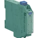
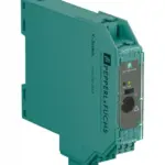
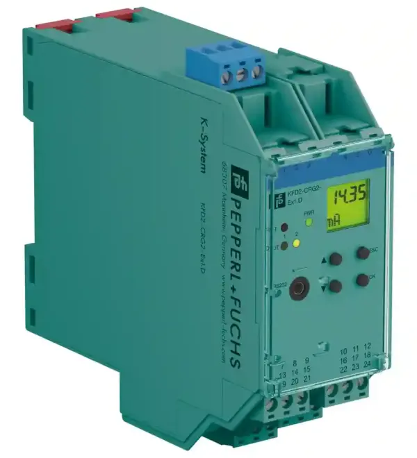
Pepperl Fuchs KFD2-CRG2-Ex1.D
Transmitter Power Supply. 1-channel isolated barrier, 24 V DC supply (Power Rail), Input 2-wire and 3-wire transmitters and 2-wire current sources, Output 0/4 mA … 20 mA, 2 relay contact outputs, Ad…
Request for Quote
Shipping & Delivery
-
 Courier delivery
Our courier will deliver to the specified address
5-6 Days
From €20
-
 DHL Courier delivery
DHL courier will deliver to the specified address
2-3 Days
From €40
-
 Warranty 1 year
-
 Free 30-Day returns
Description
Transmitter Power Supply. 1-channel isolated barrier, 24 V DC supply (Power Rail), Input 2-wire and 3-wire transmitters and 2-wire current sources, Output 0/4 mA … 20 mA, 2 relay contact outputs, Adjustable energized/de-energized delay, Programmable high/low alarm, Linearization function (max 20 points), Line fault detection (LFD), Up to SIL 2 acc. to IEC/EN 61508 / IEC/EN 61511, Housing width: 40 mm, Number of channels: 1-channel, Trip relay, Safety Integrity Level (SIL): SIL 2, Rated voltage: 20 … 30 V DC. Signal type: Analog input. Safety Integrity Level (SIL): SIL 2. Connection: Power Rail or terminals 23+, 24-. Rated voltage: 20 … 30 V DC. Rated current: approx. 130 mA. Power dissipation: 2 W. Power consumption: 2.5 W. Programming interface: programming socket. Connection side: field side. Connection: terminals 1, 2, 3. Input I: . Input signal0/4 … 20 mAAvailable voltage≥ 15 V at 20 mAOpen circuit voltage/short-circuit current24 V / 33 mAInput resistance45 Ω (terminals 2, 3)Line fault detectionbreakage I 22 mA: . Input signal: 0/4 … 20 mA. Available voltage: ≥ 15 V at 20 mA. Open circuit voltage/short-circuit current: 24 V / 33 mA. Input resistance: 45 Ω (terminals 2, 3). Line fault detection: breakage I 22 mA. Connection side: control side. Connection: output I: terminals 10, 11, 12 output II: terminals 16, 17, 18 output III: terminals 8+, 7-. Output signal: 0 … 20 mA or 4 … 20 mA. Output I, II: signal, relay. Contact loading253 V AC / 2 A / cos φ ≥ 0.7 ; 40 V DC / 2 AMechanical life5 x 107 switching cycles: . Contact loading: 253 V AC / 2 A / cos φ ≥ 0.7 ; 40 V DC / 2 A. Mechanical life: 5 x 10⁷ switching cycles. Output III: Signal, analog. Current range0 … 20 mA or 4 … 20 mAOpen loop voltagemax. 24 V DCLoadmax. 650 ΩFault signaldownscale I ≤ 3.6 mA, upscale I ≥ 21 mA (acc. NAMUR NE43): . Current range: 0 … 20 mA or 4 … 20 mA. Open loop voltage: max. 24 V DC. Load: max. 650 Ω. Fault signal: downscale I ≤ 3.6 mA, upscale I ≥ 21 mA (acc. NAMUR NE43). Energized/De-energized delay: 0 … 250 s , adjustable. Input I: . Accuracy< 30 µAInfluence of ambient temperature0.003 %/K (30 ppm): . Accuracy: < 30 µA. Influence of ambient temperature: 0.003 %/K (30 ppm). Output I, II: . Response delay≤ 200 ms at bounce from 0 … 20 mA: . Response delay: ≤ 200 ms at bounce from 0 … 20 mA. Output III: . Resolution≤ 10 µAAccuracy< 20 µAInfluence of ambient temperature0.005 %/K (50 ppm)Reaction time< 650 ms at bounce from 0 … 20 mA at the input, 90 % of output full-scale value: . Resolution: ≤ 10 µA. Accuracy: < 20 µA. Influence of ambient temperature: 0.005 %/K (50 ppm). Reaction time: < 650 ms at bounce from 0 … 20 mA at the input, 90 % of output full-scale value. Input/Other circuits: reinforced insulation according to IEC/EN 61010-1, rated insulation voltage 300 Veff. Output I, II/other circuits: reinforced insulation according to IEC/EN 61010-1, rated insulation voltage 300 Veff. Mutual output I, II, III: reinforced insulation according to IEC/EN 61010-1, rated insulation voltage 300 Veff. Output III/power supply and collective error: functional insulation acc. to IEC 62103, rated insulation voltage 50 Veff. Interface/power supply and collective error: functional insulation acc. to IEC 62103, rated insulation voltage 50 Veff. Display elements: LEDs , display. Control elements: Control panel. Configuration: via operating buttons via PACTware. Labeling: space for labeling at the front. Electromagnetic compatibility: . Directive 2014/30/EUEN 61326-1:2013 (industrial locations): . Directive 2014/30/EU: EN 61326-1:2013 (industrial locations). Low voltage: . Directive 2014/35/EUEN 61010-1:2010: . Directive 2014/35/EU: EN 61010-1:2010. Electromagnetic compatibility: NE 21:2006. Degree of protection: IEC 60529:2001. Ambient temperature: -20 … 60 °C (-4 … 140 °F). Degree of protection: IP20. Connection: screw terminals. Mass: 300 g. Dimensions: 40 x 119 x 115 mm (1.6 x 4.7 x 4.5 inch) (W x H x D) , housing type C2. Mounting: on 35 mm DIN mounting rail acc. to EN 60715:2001. EU-type examination certificate: TÜV 01 ATEX 1701. Marking II (1)G [Ex ia Ga] IIC [exsign] II (1)D [Ex ia Da] IIIC [exsign] I (M1) [Ex ia Ma] IInputEx ia: . Marking: II (1)G [Ex ia Ga] IIC [exsign] II (1)D [Ex ia Da] IIIC [exsign] I (M1) [Ex ia Ma] I. Input: Ex ia. Supply: . Maximum safe voltageUm40 V DC (Attention! The rated voltage can be lower.): Um. Maximum safe voltage: 40 V DC (Attention! The rated voltage can be lower.). Equipment: terminals 1+, 3-. VoltageUo25.8 VCurrentIo93 mAPowerPo0.603 W: Uo. Voltage: 25.8 V. Current: 93 mA. Power: 0.603 W. Equipment: terminals 2-, 3. VoltageUi< 30 VCurrentIi115 mAVoltageUo5 VCurrentIo0.3 mAPowerPo0.3 mW: Ui. Voltage: 0.7; 40 V DC/2 A resistive load: Um. Maximum safe voltage: 253 V AC / 40 V DC (Attention! Um is no rated voltage.). Contact loading: 253 V AC/2 A/cos φ > 0.7; 40 V DC/2 A resistive load. Output III: terminals 8+, 7- non-intrinsically safe. Maximum safe voltage UmUm40 V (Attention! The rated voltage can be lower.): Um. Maximum safe voltage Um: 40 V (Attention! The rated voltage can be lower.). Interface: RS 232. Maximum safe voltageUm40 V (Attention! The rated voltage can be lower.) , RS 232: Um. Maximum safe voltage: 40 V (Attention! The rated voltage can be lower.) , RS 232. Certificate: TÜV 02 ATEX 1885 X. Marking II 3G Ex nA nC IIC T4: . Marking: II 3G Ex nA nC IIC T4. Output I, II: . Contact loading50 V AC/2 A/cos φ > 0.7; 40 V DC/2 A resistive load: . Contact loading: 50 V AC/2 A/cos φ > 0.7; 40 V DC/2 A resistive load. Galvanic isolation: . Input/Other circuitssafe electrical isolation acc. to IEC/EN 60079-11, voltage peak value 375 V: . Input/Other circuits: safe electrical isolation acc. to IEC/EN 60079-11, voltage peak value 375 V. Directive conformity: . Directive 2014/34/EUEN 60079-0:2012+A11:2013 , EN 60079-11:2012 , EN 60079-15:2010: . Directive 2014/34/EU: EN 60079-0:2012+A11:2013 , EN 60079-11:2012 , EN 60079-15:2010. FM approval: . Control drawing16-554FM-12 (cFMus): . Control drawing: 16-554FM-12 (cFMus). UL approval: E223772. IECEx approval: . IECEx certificateIECEx TUN 09.0007 IECEx TSA 18.0007XIECEx marking[Ex ia Ga] IIC, [Ex ia Da] IIIC, [Ex ia Ma] I Ex ec nC IIC T4 Gc: . IECEx certificate: IECEx TUN 09.0007 IECEx TSA 18.0007X. IECEx marking: [Ex ia Ga] IIC, [Ex ia Da] IIIC, [Ex ia Ma] I Ex ec nC IIC T4 Gc. Supplementary information: Observe the certificates, declarations of conformity, instruction manuals, and manuals where applicable. For information see www.pepperl-fuchs.com.
Specification
General specifications
| Signal type | Analog input |
|---|
Functional safety related parameters
| Safety Integrity Level (SIL) | SIL 2 |
|---|
Supply
| Connection | Power Rail or terminals 23+, 24- |
|---|---|
| Rated voltage | 20 ... 30 V DC |
| Rated current | approx. 130 mA |
| Power dissipation | 2 W |
| Power consumption | 2.5 W |
Interface
| Programming interface | programming socket |
|---|
Input
| Connection side | field side |
|---|---|
| Connection | terminals 1, 2, 3 |
| Input I | |
| Input signal0/4 ... 20 mAAvailable voltage≥ 15 V at 20 mAOpen circuit voltage/short-circuit current24 V / 33 mAInput resistance45 Ω (terminals 2, 3)Line fault detectionbreakage I < 0.2 mA; short-circuit I > 22 mA | |
| Input signal | 0/4 ... 20 mA |
| Available voltage | ≥ 15 V at 20 mA |
| Open circuit voltage/short-circuit current | 24 V / 33 mA |
| Input resistance | 45 Ω (terminals 2, 3) |
| Line fault detection | breakage I < 0.2 mA; short-circuit I > 22 mA |
Output
| Connection side | control side |
|---|---|
| Connection | output I: terminals 10, 11, 12 output II: terminals 16, 17, 18 output III: terminals 8+, 7- |
| Output signal | 0 ... 20 mA or 4 ... 20 mA |
| Output I, II | signal, relay |
| Contact loading253 V AC / 2 A / cos φ ≥ 0.7 ; 40 V DC / 2 AMechanical life5 x 107 switching cycles | |
| Contact loading | 253 V AC / 2 A / cos φ ≥ 0.7 ; 40 V DC / 2 A |
| Mechanical life | 5 x 10⁷ switching cycles |
| Output III | Signal, analog |
| Current range0 ... 20 mA or 4 ... 20 mAOpen loop voltagemax. 24 V DCLoadmax. 650 ΩFault signaldownscale I ≤ 3.6 mA, upscale I ≥ 21 mA (acc. NAMUR NE43) | |
| Current range | 0 ... 20 mA or 4 ... 20 mA |
| Open loop voltage | max. 24 V DC |
| Load | max. 650 Ω |
| Fault signal | downscale I ≤ 3.6 mA, upscale I ≥ 21 mA (acc. NAMUR NE43) |
| Energized/De-energized delay | 0 ... 250 s , adjustable |
Transfer characteristics
| Input I | |
|---|---|
| Accuracy< 30 µAInfluence of ambient temperature0.003 %/K (30 ppm) | |
| Accuracy | < 30 µA |
| Influence of ambient temperature | 0.003 %/K (30 ppm) |
| Output I, II | |
| Response delay≤ 200 ms at bounce from 0 ... 20 mA | |
| Response delay | ≤ 200 ms at bounce from 0 ... 20 mA |
| Output III | |
| Resolution≤ 10 µAAccuracy< 20 µAInfluence of ambient temperature0.005 %/K (50 ppm)Reaction time< 650 ms at bounce from 0 ... 20 mA at the input, 90 % of output full-scale value | |
| Resolution | ≤ 10 µA |
| Accuracy | < 20 µA |
| Influence of ambient temperature | 0.005 %/K (50 ppm) |
| Reaction time | < 650 ms at bounce from 0 ... 20 mA at the input, 90 % of output full-scale value |
Galvanic isolation
| Input/Other circuits | reinforced insulation according to IEC/EN 61010-1, rated insulation voltage 300 Veff |
|---|---|
| Output I, II/other circuits | reinforced insulation according to IEC/EN 61010-1, rated insulation voltage 300 Veff |
| Mutual output I, II, III | reinforced insulation according to IEC/EN 61010-1, rated insulation voltage 300 Veff |
| Output III/power supply and collective error | functional insulation acc. to IEC 62103, rated insulation voltage 50 Veff |
| Interface/power supply and collective error | functional insulation acc. to IEC 62103, rated insulation voltage 50 Veff |
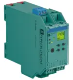
Indicators/settings
| Display elements | LEDs , display |
|---|---|
| Control elements | Control panel |
| Configuration | via operating buttons via PACTware |
| Labeling | space for labeling at the front |
Directive conformity
| Electromagnetic compatibility | |
|---|---|
| Directive 2014/30/EUEN 61326-1:2013 (industrial locations) | |
| Directive 2014/30/EU | EN 61326-1:2013 (industrial locations) |
| Low voltage | |
| Directive 2014/35/EUEN 61010-1:2010 | |
| Directive 2014/35/EU | EN 61010-1:2010 |
Conformity
| Electromagnetic compatibility | NE 21:2006 |
|---|---|
| Degree of protection | IEC 60529:2001 |
Ambient conditions
| Ambient temperature | -20 ... 60 °C (-4 ... 140 °F) |
|---|
Mechanical specifications
| Degree of protection | IP20 |
|---|---|
| Connection | screw terminals |
| Mass | 300 g |
| Dimensions | 40 x 119 x 115 mm (1.6 x 4.7 x 4.5 inch) (W x H x D) , housing type C2 |
| Mounting | on 35 mm DIN mounting rail acc. to EN 60715:2001 |
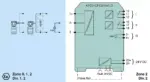
Data for application in connection with hazardous areas
| EU-type examination certificate | TÜV 01 ATEX 1701 |
|---|---|
| Marking II (1)G [Ex ia Ga] IIC [exsign] II (1)D [Ex ia Da] IIIC [exsign] I (M1) [Ex ia Ma] IInputEx ia | |
| Marking | II (1)G [Ex ia Ga] IIC [exsign] II (1)D [Ex ia Da] IIIC [exsign] I (M1) [Ex ia Ma] I |
| Input | Ex ia |
| Supply | |
| Maximum safe voltageUm40 V DC (Attention! The rated voltage can be lower.) | Um |
| Maximum safe voltage | 40 V DC (Attention! The rated voltage can be lower.) |
| Equipment | terminals 1+, 3- |
| VoltageUo25.8 VCurrentIo93 mAPowerPo0.603 W | Uo |
| Voltage | 25.8 V |
| Current | 93 mA |
| Power | 0.603 W |
| Equipment | terminals 2-, 3 |
| VoltageUi< 30 VCurrentIi115 mAVoltageUo5 VCurrentIo0.3 mAPowerPo0.3 mW | Ui |
| Voltage | < 30 V |
| Current | 115 mA |
| Voltage | 5 V |
| Current | 0.3 mA |
| Power | 0.3 mW |
| Equipment | terminals 1+, 2 / 3- |
| VoltageUo25.8 VCurrentIo112 mAPowerPo720 mW | Uo |
| Voltage | 25.8 V |
| Current | 112 mA |
| Power | 720 mW |
| Output I, II | terminals 10, 11, 12; 16, 17, 18 non-intrinsically safe |
| Maximum safe voltageUm253 V AC / 40 V DC (Attention! Um is no rated voltage.)Contact loading253 V AC/2 A/cos φ > 0.7; 40 V DC/2 A resistive load | Um |
| Maximum safe voltage | 253 V AC / 40 V DC (Attention! Um is no rated voltage.) |
| Contact loading | 253 V AC/2 A/cos φ > 0.7; 40 V DC/2 A resistive load |
| Output III | terminals 8+, 7- non-intrinsically safe |
| Maximum safe voltage UmUm40 V (Attention! The rated voltage can be lower.) | Um |
| Maximum safe voltage Um | 40 V (Attention! The rated voltage can be lower.) |
| Interface | RS 232 |
| Maximum safe voltageUm40 V (Attention! The rated voltage can be lower.) , RS 232 | Um |
| Maximum safe voltage | 40 V (Attention! The rated voltage can be lower.) , RS 232 |
| Certificate | TÜV 02 ATEX 1885 X |
| Marking II 3G Ex nA nC IIC T4 | |
| Marking | II 3G Ex nA nC IIC T4 |
| Output I, II | |
| Contact loading50 V AC/2 A/cos φ > 0.7; 40 V DC/2 A resistive load | |
| Contact loading | 50 V AC/2 A/cos φ > 0.7; 40 V DC/2 A resistive load |
| Galvanic isolation | |
| Input/Other circuitssafe electrical isolation acc. to IEC/EN 60079-11, voltage peak value 375 V | |
| Input/Other circuits | safe electrical isolation acc. to IEC/EN 60079-11, voltage peak value 375 V |
| Directive conformity | |
| Directive 2014/34/EUEN 60079-0:2012+A11:2013 , EN 60079-11:2012 , EN 60079-15:2010 | |
| Directive 2014/34/EU | EN 60079-0:2012+A11:2013 , EN 60079-11:2012 , EN 60079-15:2010 |
International approvals
| FM approval | |
|---|---|
| Control drawing16-554FM-12 (cFMus) | |
| Control drawing | 16-554FM-12 (cFMus) |
| UL approval | E223772 |
| IECEx approval | |
| IECEx certificateIECEx TUN 09.0007 IECEx TSA 18.0007XIECEx marking[Ex ia Ga] IIC, [Ex ia Da] IIIC, [Ex ia Ma] I Ex ec nC IIC T4 Gc | |
| IECEx certificate | IECEx TUN 09.0007 IECEx TSA 18.0007X |
| IECEx marking | [Ex ia Ga] IIC, [Ex ia Da] IIIC, [Ex ia Ma] I Ex ec nC IIC T4 Gc |
General information
| Supplementary information | Observe the certificates, declarations of conformity, instruction manuals, and manuals where applicable. For information see www.pepperl-fuchs.com. |
|---|
Reviews
Clear filtersThere are no reviews yet.